
Pivot Points Alignment
Pivot Points Alignment
This alignment should be used before setting up a new acquisition using a grating grid with latex beads. This alignment is very important for a subsequent collection which is using a beam tilts (Image shift).
Do not perform this directly after refilling LN2 (ideally > 3 hours), and not directly after using LOW MAG mode.
Pivot Tilt
Beam tilt pivot points
- Go to standard focus by double clicking “STD Focus” (right hand panel).
- Ensure that you are at eucentric height. Note: Use rough eucentric for a rough targeting. Measure the actual defocus in SerialEM (Menu –> Focus/Tune –> Measure defocus). The log file will display the actual defocus. Use the Z up and Z down buttons (small panel) to adjust the eucentric height. and confirm/readjust with “Measure Defocus”
- Select record beam conditions in SerialEM (pink panel, Rec.)
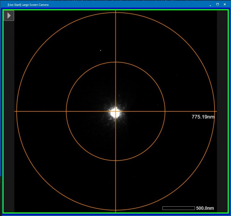
- Condense the beam to a small point (Brightness dial, left hand panel) and roughly center the beam on the large phosphor screen with “Shift X and Y”(both hand panels) (Figure 1).
- Insert small phosphor screen “FS retract” right hand panel.
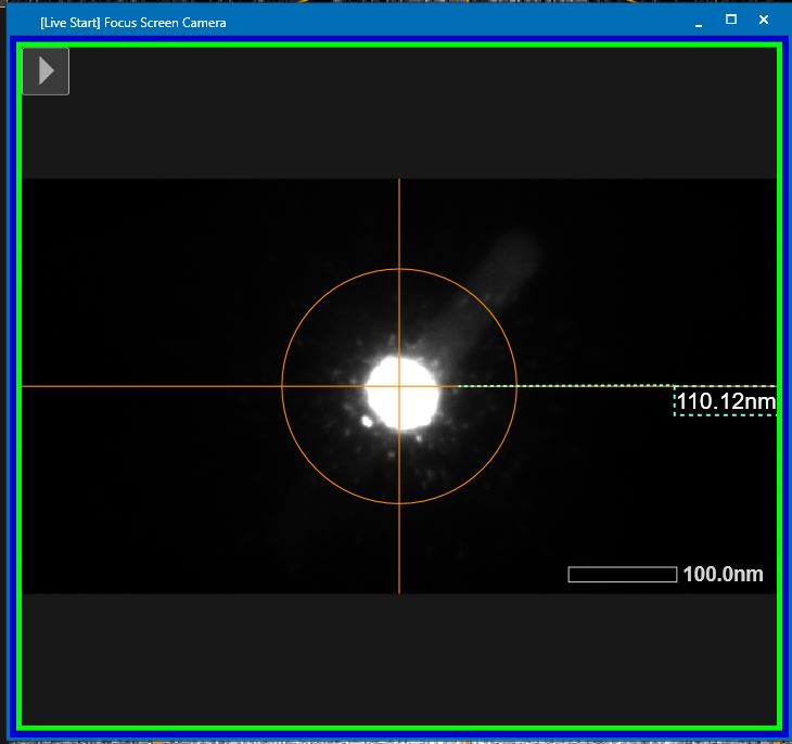
- Condense the beam further into a very small dot (Brightness dial, left hand panel) and center the beam on this screen with “Shift X and Y” (both hand panels) (Figure 2).
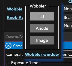
- Open the wobbler window in TEM center through the “Lens/Deflector” window by hovering over “Wobbler” and clicking on “Wobbler window” (Figure 3).
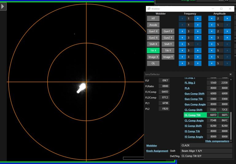
- Select in the new window “Tilt X” (Figure 4). CL Comp tilt will be automatically assigned to the Def/Stig knobs.
- Use “Def/Stig X” knob (left hand panel) and minimize the displacement of the major beam. Note: You can use Beam shift if you will lose the beam from the small Phosphor Screen.
- Switch off “Tilt X” and switch on “Tilt Y”.
- Use “Def/Stig Y” knob (left hand panel) and minimize the displacement of the major beam. Note: You can use Beam shift if you will lose the beam from the small Phosphor Screen.
- Switch off “Tilt Y”.
Beam Tilt
As above you still need to be at standard focus and eucentric height.
- Remove the Small Focus Screen (“FS insert”, right hand panel)
- Put the beam in parallel mode by clicking “Parallel” in the microscope pictogram. It will be highlighted green.

- Center the image with the phosphor screen using the stage on one of the latex beads, center the beam (Figure 5).
- Insert the small focus screen “FScreen retract”, (right hand panel).
- Center the latex bead on the screen using the trackball.
- Paint a circle around the position of the latex bead (TEM Center menu –> Tools –> Ellipse)
- Change the defocus to -10 to -15 um (“Image/diff focus button”, right hand panel).
- Switch on “Bright tilt” (Left hand panel). This will assign BeamAlign2 to the Def/Stig knobs.
- Center the latex bead again on its original position using “Def/Stig X&Y” buttons (both hand panels).
- Hit standard focus (Std focus, right hand panel).
- Repeat above procedure until the bead does not change its position during defocusing.
- Switch off “Bright tilt” (Left hand panel).
Pivot Shift
Beam shift pivot points
From before you should still be at standard focus and eucentric height. You should also still have a latex bead in the center of the focus screen
- Remove condenser lens aperture (CL button, microscope pictogram, TEM center).
- Set defocus to . -40 um (“Image/Diff focus” button, right hand panel).
- In the Lens/Deflector window hover over “CL Comp Shift” and push “assign to knobs”.
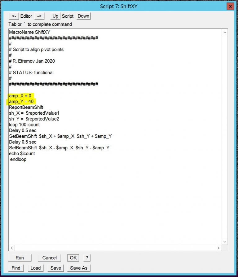
- In SerialEM edit the script Shift X,Y (menu –> Script –> Edit –> Edit 6 (or similar)) and put amp_X to 40 and amp_Y to 0, then run script Shift X,Y (Figure 8).
- Minimize the movement of the latex bead along the beam motion on the focusing screen using “Def/Stig X”button.
- If you see lateral motion against the beam motion, assign “CL Comp Angle” to the knobs (via Lens/Deflector window –> CL Comp Angle –> Assign to knobs”.
- Click on one of the “Def/Stig” button to go into coarse mode.
- Use the “Def/Stig X”button to minimize the lateral motion against the beam shift.
- Click on one of the “Def/Stig” button to go back into fine mode.
- Stop script execution in Serial EM (dark green panel, “STOP”)
- Set BEAM ALIGN 1 to default by hovering in the LEns/Deflector window over Beam Align 1 and hit “Default”.
- Edit script Shift X,Y and put amp_X to 0 and amp_Y to 40, then run script Shift X,Y (Figure 8).
- Minimize the movement of the latex bead along the beam motion on the focusing screen using “Def/Stig Y”button.
- If you see lateral motion against the beam motion, assign “CL Comp Angle” to the knobs (via Lens/Deflector window –> CL Comp Angle –> Assign to knobs”.
- Click on one of the “Def/Stig” button to go into coarse mode.
- Use the “Def/Stig Y”button to minimize the lateral motion against the beam shift.
- Click on one of the “Def/Stig” button to go back into fine mode.
- Stop script execution in Serial EM (dark green panel, “STOP”)
- Unassign “CL Comp Angle” from the knobs (via Lens/Deflector window –> CL Comp Angle –> Assign to knobs”). Button will not be green anymore.
- Set BEAM ALIGN 1 to default by hovering in the LEns/Deflector window over Beam Align 1 and hit “Default”.
- Insert condenser lens aperture (CL button, microscope pictogram, TEM center).
- Push STANDARD FOCUS (“STD focus”, right hand panel).
- Center the beam with “Shift X&Y” button (both hand panels).