
SerialEM Grid Atlas
SerialEM Grid Atlas
Preparing a grid atlas
Note: Following procedure assumes that you are still in Low Dose Mode (pink panel)

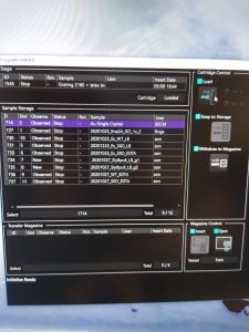
- Insert the grid you want to measure onto the stage by selecting it in the Cryospecporter window and clicking on load (Figure 1). Note: It will automatically unload any sample currently on the stage.
- Open the beam valve (beam button, left hand panel).

- In the pink SerialEM panel select “Vie.” to load the view microscope parameters (Figure 2).
- Put down the large phosphor screen (right hand panel, screen retract)
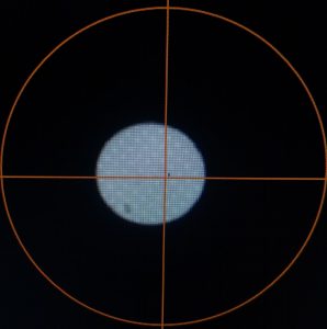
- Move the stage with the trackball until you see a square in the center of the field of view (Figure 3). Note: Skip this for now if you can’t find a square close by and do it after the atlas is collected. (Update Z of map)

- Move the stage to eucentric height using serialEM, by clicking in the menu on “Task –> Eucentric Rough” (Figure 4).
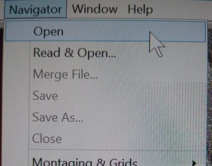
- Open a new navigator window via “Menu –> Navigator –> Open” (Figure 5).
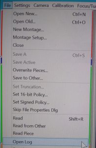
- Open a new log file via “Menu –> File –> Open Log” (Figure 6).
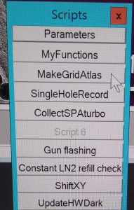
- Click in the scripts panel on “MakeGridAtlas” to start the atlas collection procedure (Figure 7).

Figure 8: Create working directory
- Create the a new working directory under “X:\Serial_EM_raw_data\myGroup” and click “OK”(Figure 8).

- Once the atlas is collected a new window will appear to save the navigator file. Ensure you are in your working directory and save the file as “navigator”. Click “Save” (Figure 9).
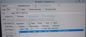
- In the navigator file a Blue labelled line will appear with the name “Sec 0- Atlas.mrc”. Double click on this line to open the map in a higher resolution (Figure 10).
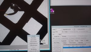
- In the navigator window select “Add points” and select in the map an easily identifiable feature. Left click on that feature add the point in the navigator window. Finally click “Stop Adding” in the Navigator window (Figure 11).
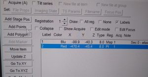
- Make sure that the newly added point is highlighted in the Navigator window and select “Go to XYZ” (Figure 12).
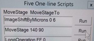
- In the One-line Scripts window “Run” the script “MoveStage 15 90” (Figure 13). Note: The recommended offset changes over longer time and may be adjusted if necessary.
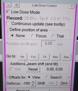
- In the pink SerialEM panel select “Go to”: “Vie.” (This is view mode) (Figure 14).

- Remove the CL aperture by double clicking on “CL” in the microscope pictogram in “TEM center” (Figure 15).
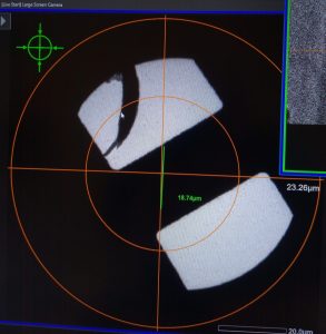
- Put down the large phosphor screen (screen retract, right hand panel). The selected feature should be close by (Figure 16).
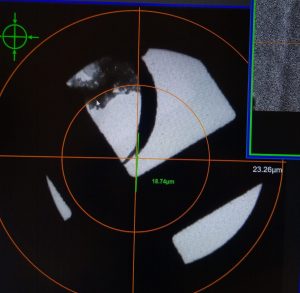
- Use the trackball to move the stage directly on top of the feature you selected on the Atlas image (Figure 17).
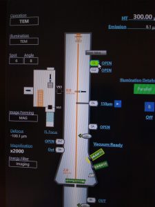
- Re-Insert CL aperture by double clicking on “CL” in the microscope pictogram in the “TEM center” (Figure 18).
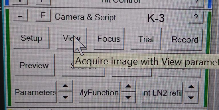
- In Serial EM click on View (dark green panel) to make a single view image with the camera (Figure 19).
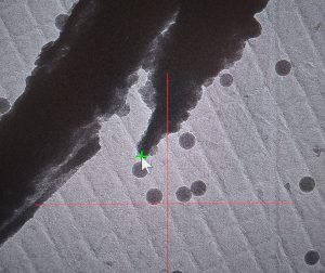
- On the View image mark the same part of your feature you selected on the atlas with a left click. A green cross will appear (Figure 20).
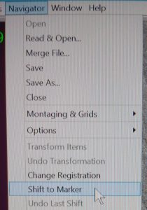
- Ensure that the marker point is still highlighted in the navigator window on click in the Menu bar on “Navigator –> Shift to Marker” (Figure 21).

- In the new pop up window you can see the shift that will be applied on the atlas map. If the numbers are completely different than the amount you used in the MoveStage command !!!!! you can update the Move stage X Y with more accurate values. Confirm the shift by clicking “Yes” (Figure 22). Note: Make sure that the displayed shift amount is reasonable otherwise you might have done something wrong.
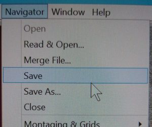
- Save the navigator file by clicking in the menu on “Navigator –> Save” (Figure 23).
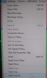
- Save the log file by clicking in the menu on “File –> Save Log As…” (Figure 24).

- Ensure that your working directory is selected and define the “File name” as “log”. Click “Save” (Figure 25).
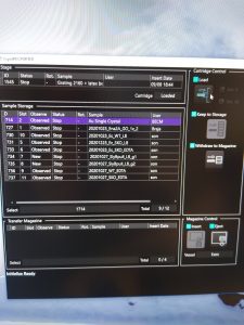
- Insert the next grid by highlighting the sample in the “CryoSpecPorter” window and clicking on “Load” (Figure 26).
- Repeat the procedure from Step 2 for all other grids you inserted. Once all grids are done continue with next step.