
CryoARM300 data collection SPA (Koehler illumination, std)
Setup of SPA data collection std
This is being actively updated at the moment
- Post bake out
- Clipping cartridges
- Taking over the microscope
- Sample insertion/removal
- Prepare gain reference
- Atlas collection (Multi-grid)
- Square ice thickness calculator
- Perform test shots
- Square imaging (Multi-Grid)
- Finding and combining holes and grabbing the hole pattern
- CL Stigmator correction
- Coma free alignment
- Search vs Record alignment
- Starting up data collection
- Unclipping cartridges
- Bake out
- Common collection problems
- SerialEM crashes and recovery
- TEM center crashes and recovery
- Gatan Camera crashes and recovery
- Calculate coma vs IS matrix
- Pivot point alignment
- Refine Beam shift calibration
- Change Liquid nitrogen tank
- Perform test shots (alternative)
Clipping cartridges
Note: All images are shown without liquid nitrogen in the workstation for easier visibility.

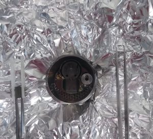
- You can find an empty magazine in the vessel wrapped in aluminium foil in the oven. Never touch it bare handed.
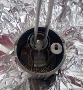
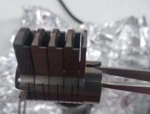
- You can pick up the magazine by putting a tweezer through the two front holes and grab it. (Figure 5 and 6)
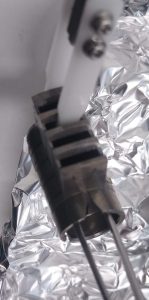
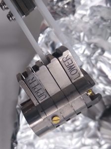
- Now grab the magazine with the white pick up tool as shown in Figure 7 and 8
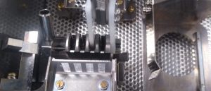
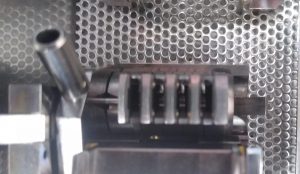
- Put the magazine into the proper position in the workstation. If done well, the magazine is sliding smoothly along the rail (Figures 9 and 10).
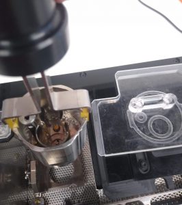
- Grab the cup tightly with the carrying tool and insert it into the workstation. Use the pictogram as a guide to know the proper rotation. It should sit tight (Figure 11).
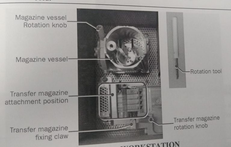
- Cool down the workstation with liquid nitrogen. Once cold, make sure that the liquid nitrogen level is not higher than the specimen attachment area (Figure 1).
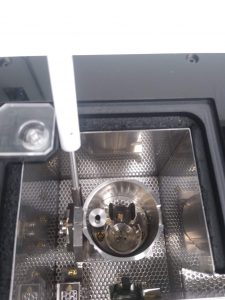
- Use the white rotation tool (Figure 1) to turn the cup 90 degrees with the opening towards the magazine (Figure 12).

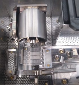
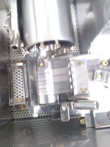
- Use the white rotation tool to turn the magazine ~90 degrees with the opening towards the assembly site (Figure 13). Once in position (Figure 14), engage the safety pin (Figure 15)
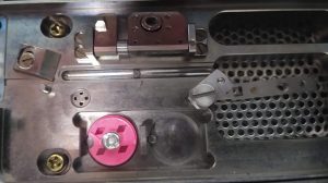
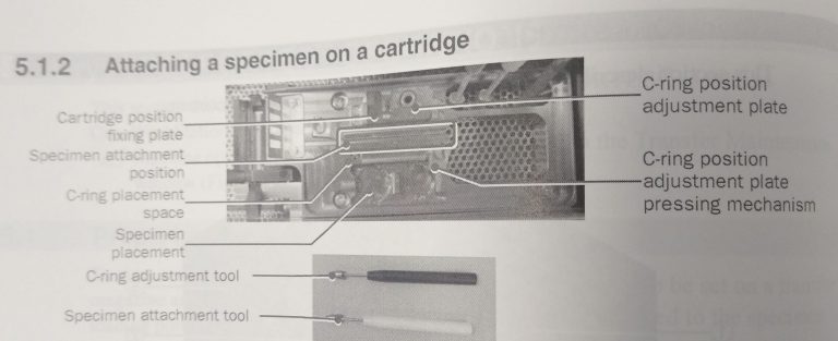
- Place the empty cartridge in the cartridge placement space (Figure 16).
- Place your grid box in the specimen placement area (Figure 16).
- Place the C-ring in the C-ring placement space (Figure 16).
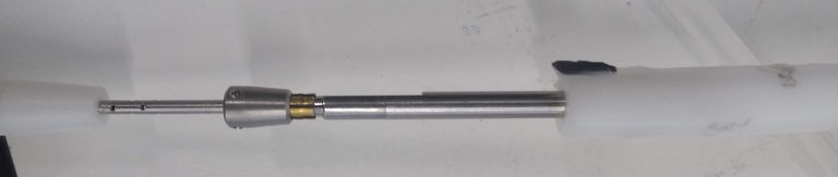
- Ensure that the tip of the specimen attachment tool is properly spread by inserting the rotation tool at the end (Figure 17).
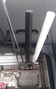
- Put a tweezer, the black C-ring adjustment tool and the white specimen attachment tool into the workstation and make sure they are cooled down before use (Figure 18).
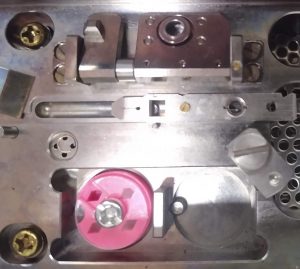
- Put a cartridge with the screw facing you and the square toward the left on the rail of the specimen attachment area (Figure 19). If properly positioned, the cartridge can slide easily sideward.
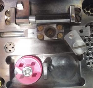
- Align the screw of the cartridge, with the hole of the C-ring adjustment plate and put down the plate. Lock it with the rotation lock (Figure 20). Note: The rotation lock here is not essential but helpful
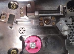
- Insert one C-ring into the C-ring adjustment plate (Figure 21). Note: The C-ring does not need to be completely flat in position, but not totally tilted either.

- Use the black C-ring adjustment tool to clamp the C-ring in the C-ring adjustment plate by pushing the tool straight down (Figure 22).
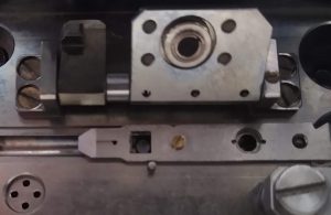
- Lift up the C-ring attachment plate and control that the C-ring is properly sitting in the plate (Figure 23). Important: It needs to be straight, otherwise clipping will fail.
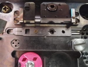
- Move the cartridge further left on the attachment position, so the open square is aligned with the square lock (Figure 24).
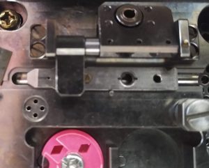
- Lock the cartridge with the square lock (Figure 25). The cartridge should not be able to move sideward anymore.
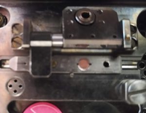
- Put your cryo grid, top side upwards, onto the cartridge. Make sure its properly positioned in the groove (Figure 26)
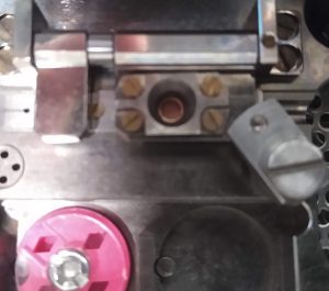
- Put down the C-ring attachment plate with the C-ring, covering the cryo grid. It is vital to use the rotation lock to rigorously lock the attachment in position (Figure 27).
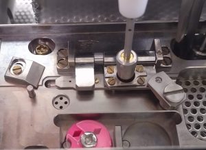
- Use the white specimen attachment tool to clip the C-ring onto the cartridge, securing the cryo grid. Important: Come down straight with the tool, no twisting, no turning (Figure 28).
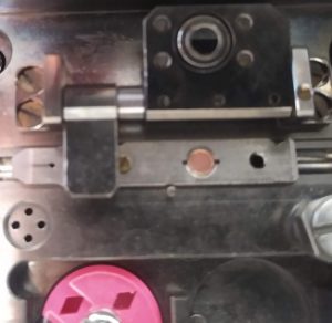
- Open the rotary lock and carefully lift up the attachment plate. If the clipring is not completely on the cartridge you can put down the attachment plate again and use the white tool again for clipping. Otherwise you can lift up the plate completely. Important: Carefully check that the clipring is properly and straight on the cartridge. (Figure 29)
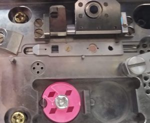
- Open the square lock from the cartridge (Figure 30).

- Slide the cartridge further left. It will automatically tilt toward you at the position shown in Figure 31.
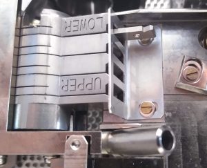
- Pick up the cartridge with a blunt tweezer and let it glide into the magazine (Figure 32). In the depicted image it is put in position 4.
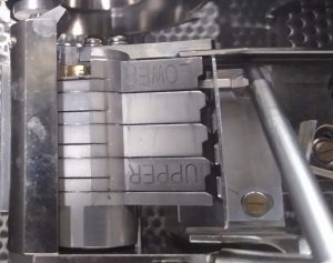
- Use the straight edge of the white rotation tool to put the cartridge tightly into the magazine. The is a small resistance to overcome (Figure 33).
- Repeat above steps for up to 4 samples.
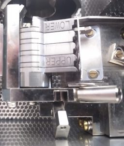
- Open the lock of the magazine (Figure 34).
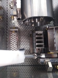
- Use the white rotation tool to turn the magazine down (Figure 35).
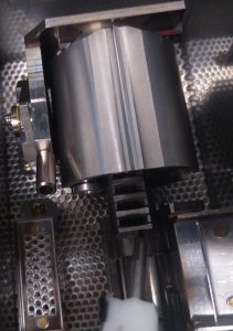
- Use the flat side of the rotation tool to push the magazine into its vessel (Figure 36).
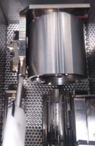
- Once the magazine is in its vessel use the white rotation tool to lift up the vessel (Figure 37).

- Once the magazine vessel is upright, fill it up with liquid nitrogen, so that the whole magazine is covered. No need to fill it up to the rim of the vessel (Figure 38) Important: Before doing the next steps, make sure the microscope is ready for grid insertion, i.e. it is not making images at the moment.

- Put the cryo cup next to the assembly workstation, have the pictogram on the lid oriented in the same direction as the magazine vessel; i.e. small and large circular structure (Figure 39)
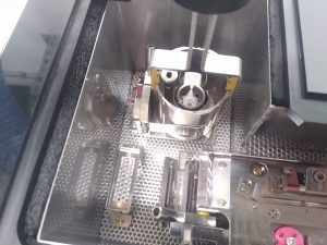
- Pick up the magazine vessel with the large grabbing tool (Figure 40). Important: Ensure a good grid to not drop the vessel.
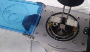
- Position the magazine vessel in the cryo cup (Figure 41). Note the proper orientation with the pictogram.
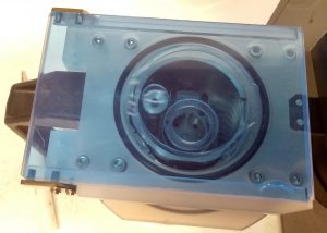
- Close the lid of the cryo cup and bring it to the microscope for insertion.
- Clean up after finishing and put all the tools back into its box and drawer.
Taking over the microscope
- Stopping the currently running data collection.
- In SerialEM click on “End Navigator” (Dark Green Panel) and wait until the last image in the cycle is recorded.
- Save navigator file by clicking “Navigator –> Save”.
- Save log file by clicking “File –> Save Log”.
- Save settings file by clicking “Settings –> Save”.
- Set Image shift back to 0 by clicking “Reset Image shift” (yellow panel).
- Check when liquid nitrogen refill is happening next. The ideal goal is to either do the liquid nitrogen refill now or after the last coma free alignment (latest in 7h).
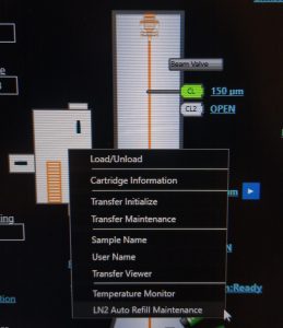
- Open the Liquid nitrogen monitor by right click on the microscope scheme in the TEM center and left click on “LN2 auto Refill Maintenance” (Figure 1)
- If it is less than 50% full, click on “refill” for “stage tank” and “transfer tank” (Figure 2)
- Wait until nitrogen filling is finished

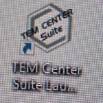
- On the microscope PC, if TEM center is not open, open TEM Center Suite launcher (Figure 3).
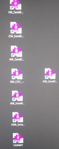
- On the camera PC, open the SerialEM executable with your desired imaging conditions (i.e. magnification and CDS/non-CDS mode) (Figure 4). We use mainly the executable 60k_CDS.
- If not yet open, open Digital Micrograph, on the camera PC by clicking on the “GSM3” executable (Figure 5).

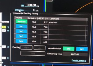
- If emission is on (visible in TEM center, on microscope scheme top right, Figure 6): In TEM center hover your mouse over “Emission” and click on “Auto Emission –> Off” (Figure 7). Wait until finished. Afterwards hover your mouse over “Emission” and click “Flashing High” (Figure 7). Once finished click on “Auto Emission –> ON”. Wait until the Emission is ramped up (It will show 10 uA). Continue at point 8. Else follow point 7.
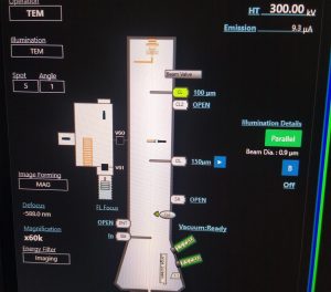
- If emission is off: In TEM center hover your mouse over “Emission” and click on “Flashing High” (Figure 7). Once finished click on “Auto Emission –> ON”. Wait until the Emission is ramped up (It will show 10 uA).
- Degauss the omega filter. Open in the TEM center the window by clicking in the menu on “Maintenance –> Filter Setting” (Figure 8).
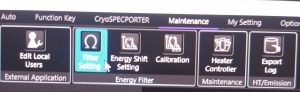
- In the Window Filter Setting click on “Degauss –> Start” (Figure 9). Note: The FL focus value is now offset and the filter will relax in the following hours. During most procedures that follow first, you can remove the Energy filter slit first, and only adjust FL focus once its really needed and probably more stable.

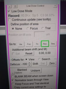
- In SerialEM, make sure you are in “Low Dose mode” and load “Record” mode (pink window, Figure 10).
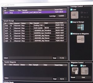
- If not yet open, open the “CryoSpecporter” window by right click on “microscope scheme (TEM center) –> Load/Unload (left click)” (Figure 11).

- Remove the grid from the stage by highlighting the stage sample and clicking on “Keep to storage” (CryoSpecporter window, Figure 12). Wait until the process is finished.
Sample insertion/removal
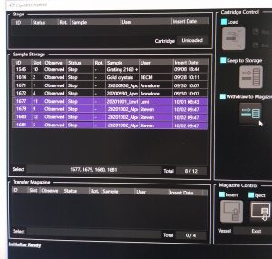
- Remove previous samples. If the magazine is still present in the microscope, select in the “CryoSpecporter” window up to 4 samples to remove and click on “Withdraw to Magazine” (Figure 1).
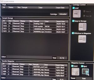
- Once the cartridges are in the transfer magazine click in the “CryoSpecporter” window on “Eject” (Figure 2).
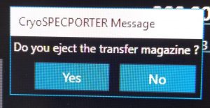
- In the newly opened window click “Yes” (Figure 3) and wait until the cup with the magazine dropped.
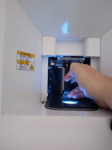
- Now you can physically remove the mug from the microscope (Figure 4&5).

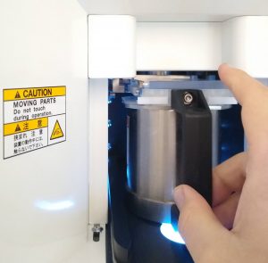
- Insert the mug with your new cartridges into the microscope by pushing the mug deep into the system. The lid will slide of automatically (Figure 6).
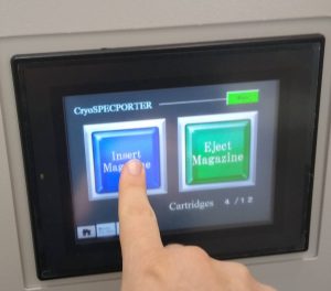
- On the touch panel on the right hand side touch to wake up the display and select “Insert Magazine” (Figure 7).
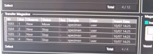
- Once the magazine is in the microscope the cartridges will be recognized by the microscope and can be seen in the “Transfer Magazine” part of the “Cryospecporter” window (Figure 8). Then the cartridges will be moved into the sample storage.
- Finally name the cartridges. Right click on the sample –> “cartridge information (left click)” (Figure 9). In the newly open window define “Sample Name” and “User Name” (Figure 10). Note: These names are not used automatically as file name of your images.
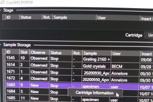
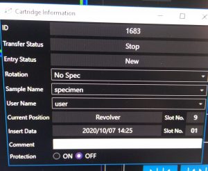
- Repeat the naming for all the cartridges you inserted.
Prepare gain reference
- If there is a grid on the stage, highlight it on the CryoSpecporter window and click "Keep to storage" (Figure 1)
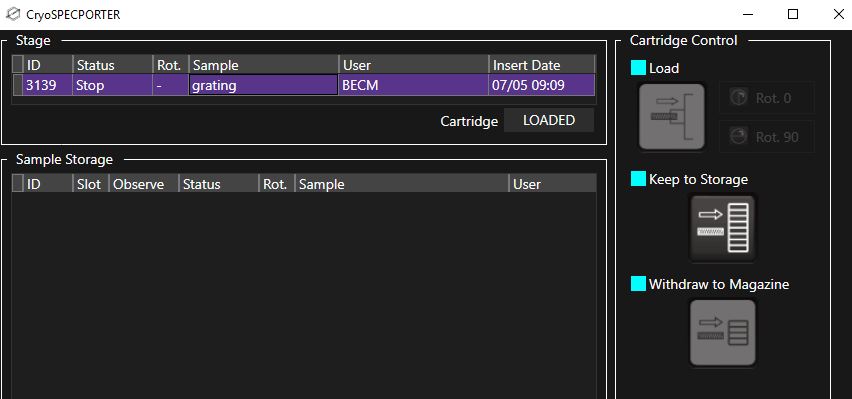
- Open Beam Valve with the “Beam” button (left hand panel).
- In SerialEM make one view image by clicking “View” (dark green panel) to ensure that the camera is in CDS or non-CDS mode (in case you use a different mode than the user before you). Note: Sometimes the camera temperature is still equilibrating (warning appears after attempting to make the image). In this case wait 5 seconds a redo the view image.
- Switch off low dose mode in SerialEM (pink panel).
- Remove the energy filter slit by pushing the “Slit In” button (right hand panel)
- Put down the large phosphor screen (Screen retract, right hand panel).
- If inserted, remove the OL aperture (double click on OL in microscope pictogram)
- Change spot size to 1 using the “Spot size” dial and 40k magnification (left hand panel)
- Center the beam with the “Shift X&Y” dials (both hand panels) and spread the beam until it covers a bit more than the inner circle on the “Large Screen Camera” (Figure 2).
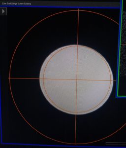
- In Digital Micrograph ensure that the Power User is activated in the menu “Help –> User –> Power User” (Figure 3).

- In Digital Micrograph, make sure that Counting mode is active under "Technique Manager --> TEM Imaging --> Counted" (Figure 4). Hint: If this is not the case the procedure will only do 1 linear gain reference.
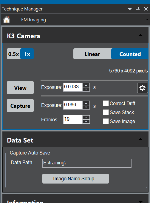
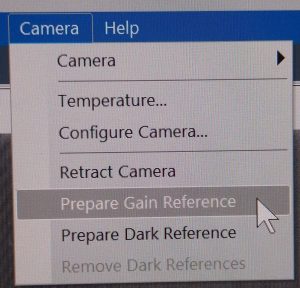
- In Digital Micrograph menu select “Camera –> Prepare Gain Reference” (Figure 5).
- Once the Dark Reference is done, lift the Phosphor Screen (“Screen Insert, right hand panel).
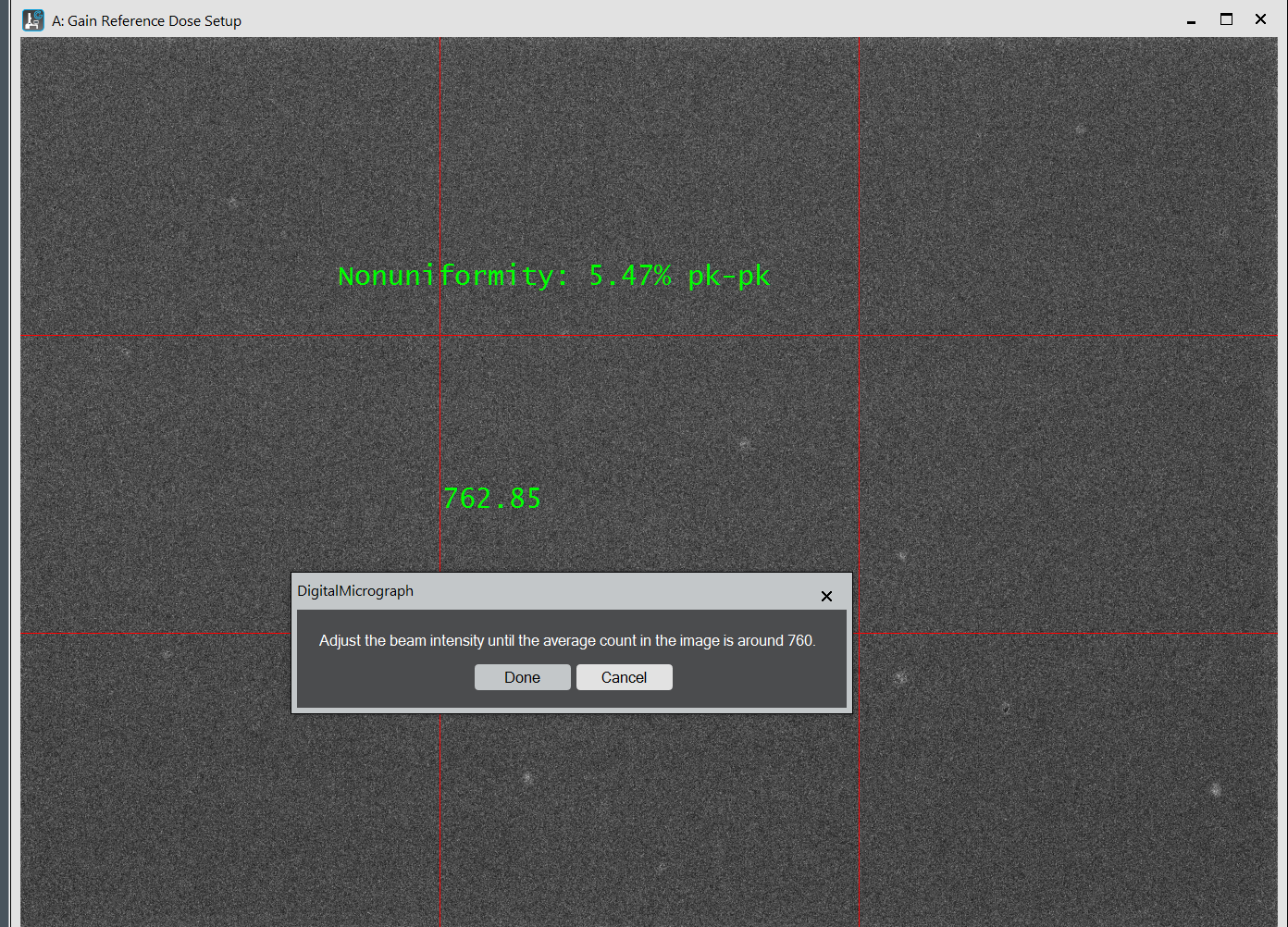
- Adjust the beam brightness (left hand panel), so that the measured dose in Digital micrograph corresponds more or less to the one requested (Should be 760) (For non-CDS Spot1 angle 3, 25k Mag, CL 100um, dose 1500). If ready, click on “done” and wait until its done (~8 minutes) (Figure 6).
- Once done, put down the phosphor screen (“Screen retract”, right hand panel).
- Change spot size to 5 (if using CDS mode) or 6 (if using non-CDS mode) using the “spot size” dial (left hand panel).
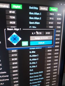
- Roughly center the beam, by hovering in the “Lens/Deflector” window over “Beam Align 1” and click on “Default” (Figure 7).
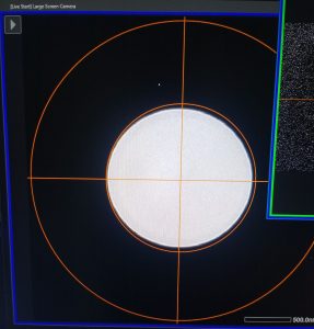
- Center the beam using the “Shift X&Y” dial (both hand panels) and spread the beam (“brightness dial”, left hand panel) until you have the beam at least fully covering the inner circle on the “Large Screen Camera” window (Figure 8).
- In the next window make sure that “expert mode” is not activated and click on “OK” (Figure 9).
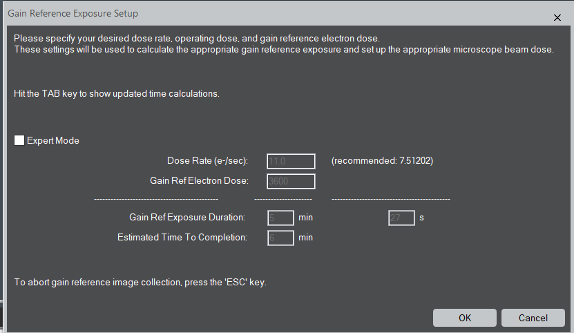
- Once the dark reference is done, lift the Phosphor screen (“Screen retract”, right hand panel).
- Adjust the beam brightness (“brightness” dial, left hand panel) until the measured dose correspond pretty well to the requested dose (usually: CDS mode 11.0, non CDS mode 20, Spot 3, angle 3, 25k) (Figure 10).
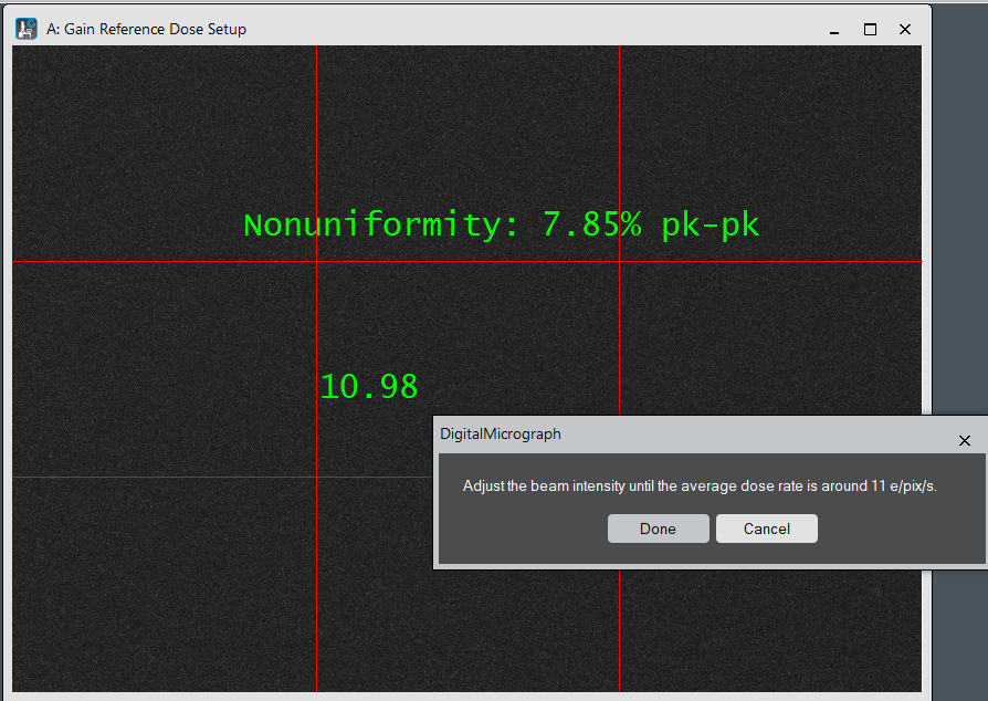
- Then, confirm the window by clicking “Done”. Wait until the procedure is done (~8 minutes).
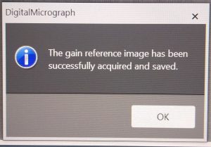
- On the next window click “OK” (Figure 11).
- In SerialEM activate “Low Dose Mode” (pink panel, Figure 12) and select record mode (“Rec.”).

- Put down the phosphor screen (Screen retract, Right hand panel).
- Center the beam using the shift X&Y dials (both hand panels).
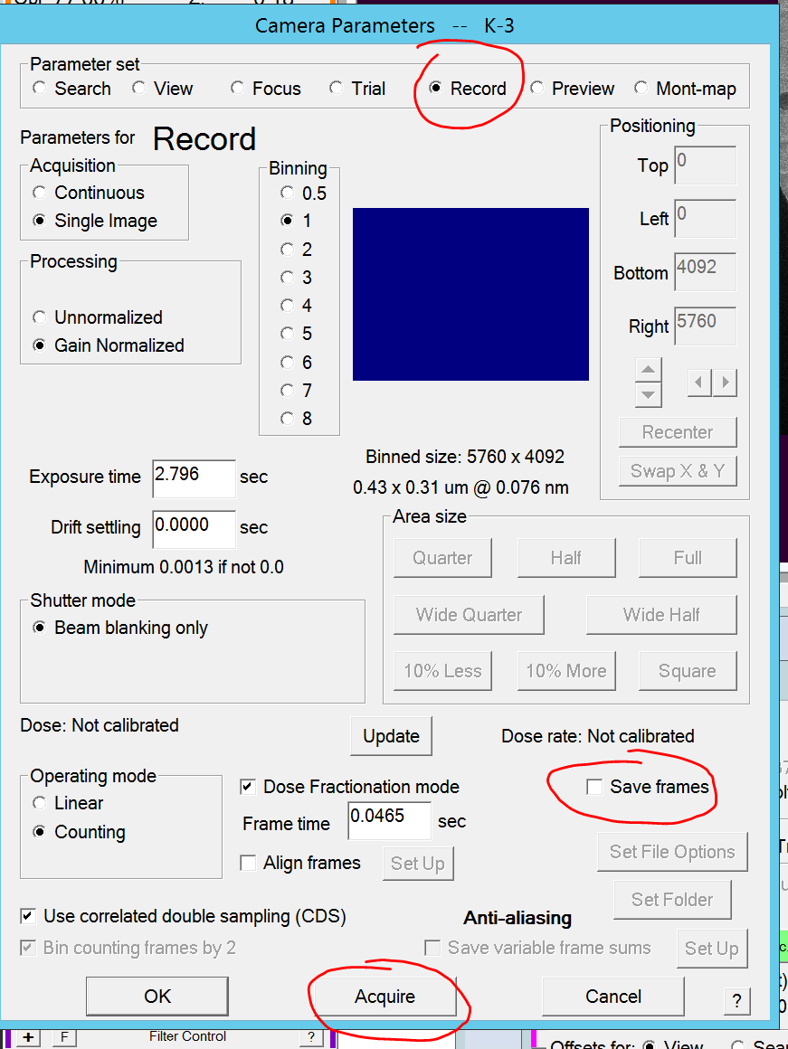
- In SerialEM click on Setup under the camera& Script panel (dark green) (Figure 13).
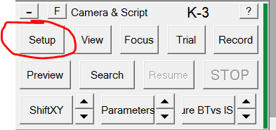
- In the new window under the record tab, ensure that "save frames" is not active (no checkbox mark). (Figure 14).
- Click on Acquire to make an image in the empty area. (Figure 14).
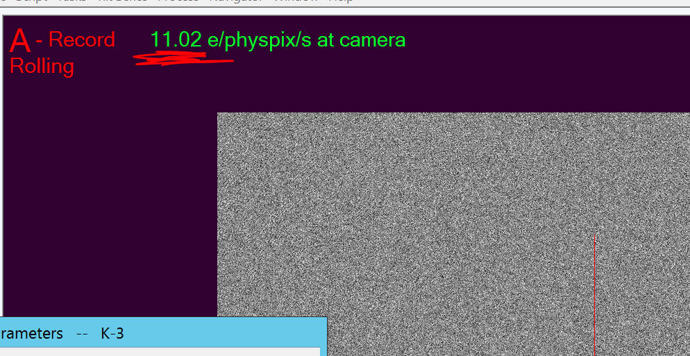
- In the SerialEM main window you see a blank image and on the top left corner you can read out the beam intensity (Figure 15)
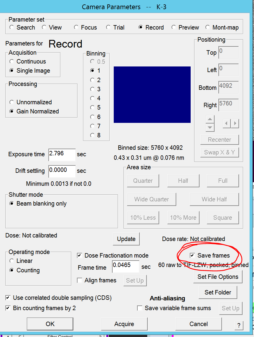
- Afterwards switch back on "save frames" under the record tab and close the window with "OK"
- Close the beam valve using the “beam” button (left hand panel).
Atlas collection (Multi-grid)
0. Make sure that you gave a useful name in the sample spec porter for each cartridge. This name will become automatically part of the sample folders created by SerialEM (Note: I avoid the date in the file name here).
Go to "Navigator --> Montaging & Grids --> Clear Multi grid Session" to remove the session of the previous user (Figure 1) (Hint: Not needed if you opened up a new executable of SerialEM)
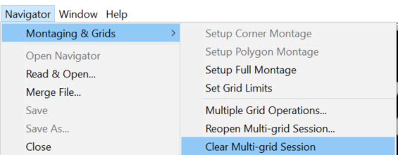
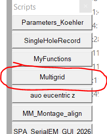
Figure 1: Clearing old Multi Grid Session - In the scripts panel click "Multigrid" to open the interface (Figure 2). It will have read and loaded your sample storage information
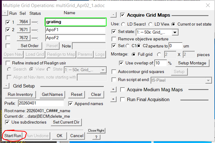
- Select the checkbox of all the grids that you want to use for Atlas Montaging (Figure 3). (Hint: Using "Set order" you can change the order of the grids during multi-grid operations)
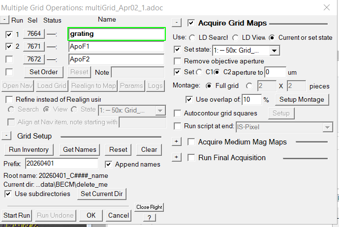
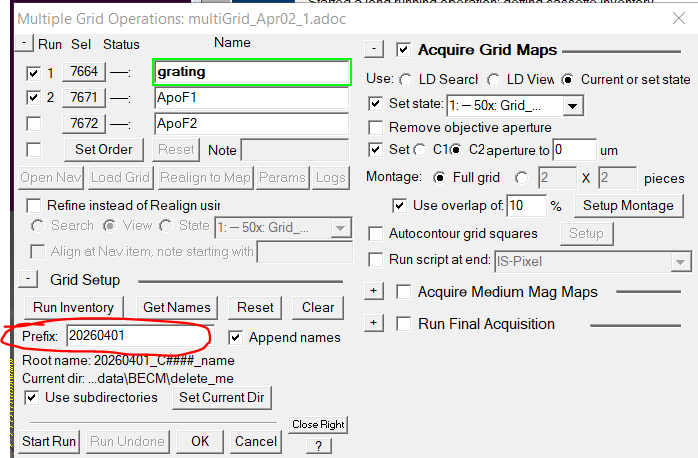
- Give a name prefix (e.g. date of collection) (Figure 4).
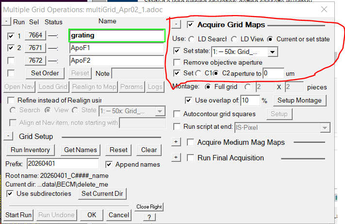
- Ensure that "Acquire Grid Maps" is selected with the proper parameters (Figure 5)
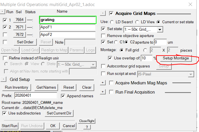
- Click on "Setup Montage" (Figure 6).
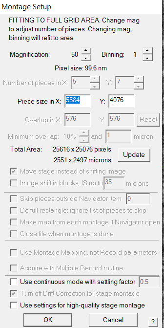
- Confirm the montage parameters and click "ok" (Figure 7).
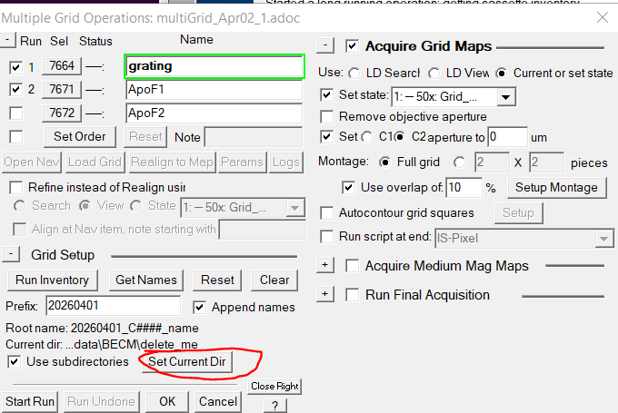
- Click on "Set Current Dir" (Figure 8)
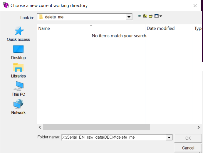
- Select your working directory at "Serial_EM_raw_data/mygroup/myfolder/" (Figure 9). (Hint: Each grid will have its own folder. Use of a subdirectory is not strictly necessary)
- Confirm with "ok".
- Click "Start Run" to start the acquisition of all grid atlases (Figure 10).
- Click on "Navigator --> Apply saved shift" to roughly fix the offset between 400x (Squares) and 50x (atlas) magnification
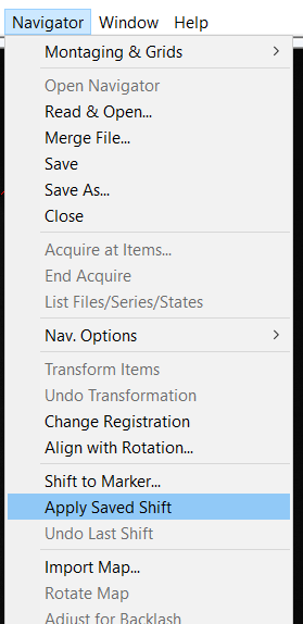
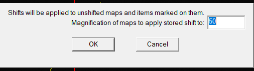
- In the newly opened window click "OK" to apply the shift to your 50x atlas map (Figure 12).
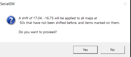
- In the new confirmation window confirm with "OK" to apply the pre-saved offset (Figure 13)
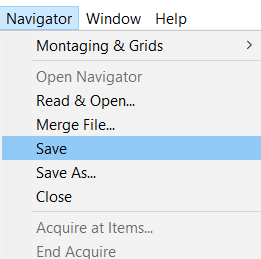
- Save the navigator with the updated coordinate system via "Navigator --> Save" (Figure 14).
- You can repeat this process now for all your other grids. Click on the ID number in the Multigrid window (here 7664) and then "Open Nav"
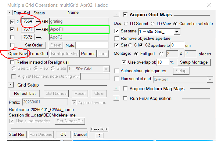
- Repeat steps 12-15 and apply saved offset and save each navigator.
If you decide later to load more grids into the microscope:
Do not use the multigrid script to start the next session (The script will create a completely new session). Just click in the multiple grids operations window on "Refresh List". This will update the list of available grids.
If you ever closed by accident the multiple grids operations window go in the menu to "Navigator --> Montaging and Grids --> Multiple grid operations"
If SerialEM closed in between you can reopen the old multiple grid operations in the menu via "Navigator --> Montaging and Grids --> Reopen multiple grid session" and find the "adoc" file of your previous collect (Date_1.adoc)
Square ice thickness calculator
This procedure is optional. It can help in distinguishing ice thicknesses of different squares.
- Open the grid atlas image by double clicking on the grid item in the navigator window (Figure 1). (Note: You can also do it automatically during the multi grid atlas procdedure by selecting the autocontour option)
- Click on "Navigator --> Montaging & Grids --> Autocontour Grid Squares" (Figure 2)
- Optional activate "Navigator --> Montaging & Grids --> Reverse Contour Colors" to inverse the colour scale (Figure 2)
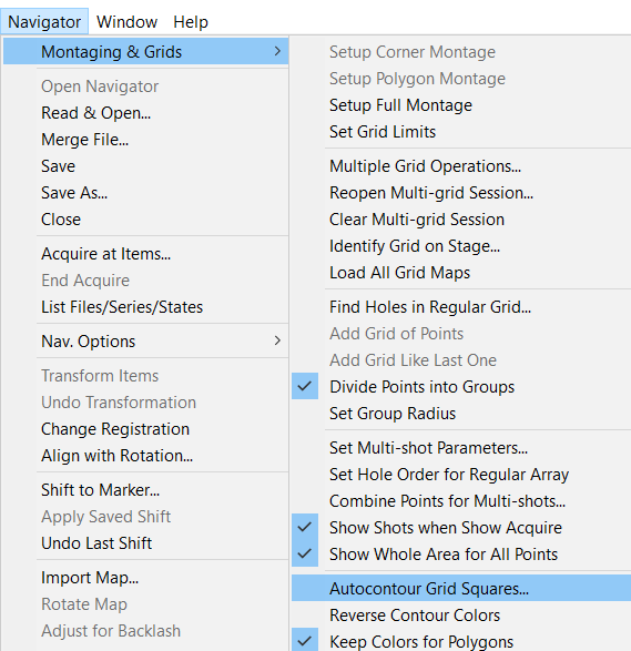
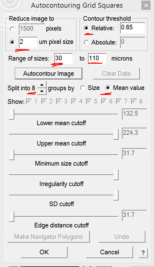
Figure 2: Autocontour grid squares - In the autocontour grid square window make sure the options shown below (Figure 3) are selected. You can adjust parameters if necessary.
- Note 1: Increasing the contour threshold may lead to the ice edge being included in the calculation, ruining the estimation
- Note 2: If you have very small or very large squares you may want to change the range of sizes values.
- Note 3: Adjusting the number of groups can give you larger 'ice bins'. The program creates groups of equivalent ice ranges not equivalent group members
- Click on "Autocontour Image" to start the procedure (Figure 3).
- Once done, each square that fits your range size will have a coloured outline from (Thick) red -> orange -> yellow -> green -> dark blue -> cyan -> violet -> magenta (thin) (Figure 4).
- Note 1: in this example some square are not marred as they were smaller than 30 microns (length of edge)
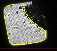
- Note 2: If you selected a good contour level it will remove the dark ice from the edge and may even remove some larger ice contaminant patches (Figure 5).
- Optional: You can adjust the 6 regulators to change thresholds. However, I did not find it impactful (Figure 4).

- Select the groups (1-8) that you want to be part of your navigator file (Figure 4).
- Click on "Make Navigator Polygons" (Figure 4).
- Click on "OK" (Figure 4).
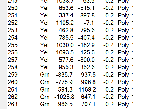
- After this you navigator file is populated with the respective squares. Each point is still labeled with the original colour from the autocontouring (Figure 6).
Perform test shots
Under this setup I recommend to make the square pictures of all the squares you would like to test shoot. This goes rather fast.
0. If not done yet, make sure to apply the saved shift from the 50x Mag Atlas to the 300/400x Square Mag for your grid via opening of the navigatoir file (step1) and then "Menu Navigator --> Apply saved shift" (see bottom of make grid atlas section for details)
- Open Navigator by selecting the ID of your grid of interest in the Multi-Grid window and click on "Open Nav" (Figure 1)
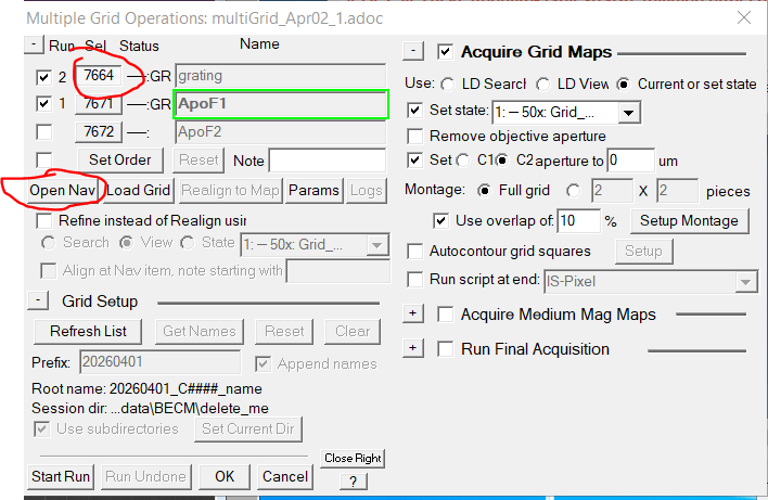
- Optional: Insert the grid in which you want to do test shots by clicking on the ID in the multigrid window. (Figure 2) Note: If there is another grid still on the stage it will be automatically unloaded. And it will be automatically loaded if you run the square imaging via multiple grids.
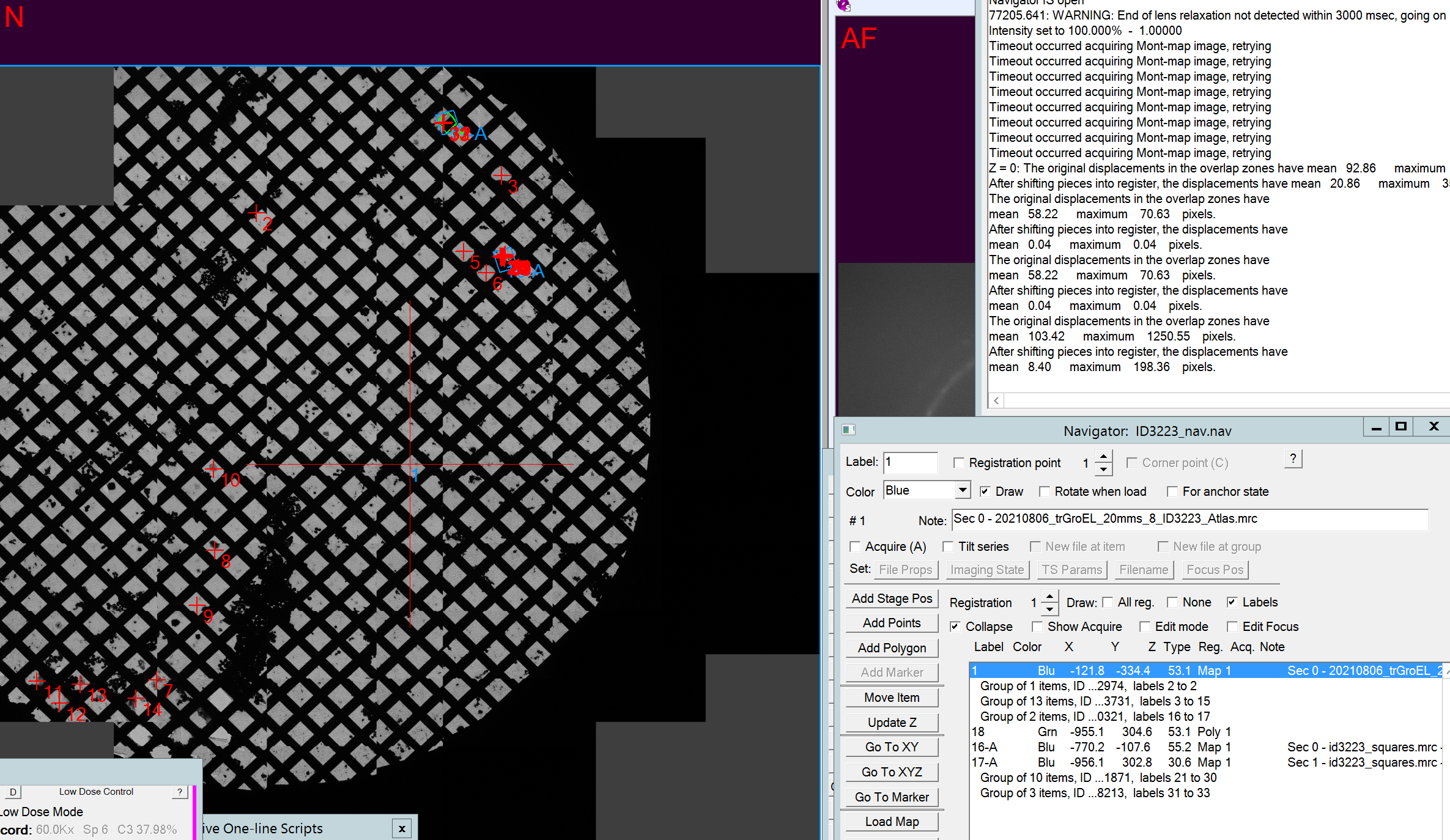
- In the navigator window double click on the item corresponding to your atlas. It is a "Blu" color item (Figure 3).
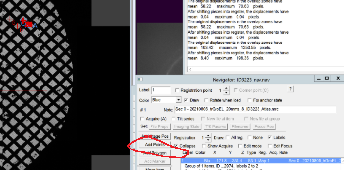
- In the navigator window click on "Add Points" and make a left click on all squares that you want to try test shots on. The points appear as red crosses in the image and "red" color item in the navigator window (Figure 4).
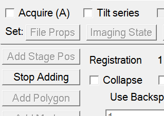
- Once finished click in the navigator window on "stop adding" (Figure 5).
- In the navigator file put all those point on acquisition by highlighting that group and clicking "A" on the keyboard. Note: If the group of point is displayed separately you can click "collapse group" checkbox
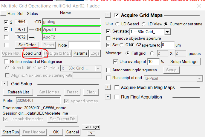
- In the Multiple Grid operations only have the checkbox on the grid active that you want to use (Figure 6)
- Make sure do remove the checkbox from "Acquire Grid Maps"
- Make sure to activate the checkbox from "Acquire Medium Mag Maps"
- Make sure the option LD View is active.
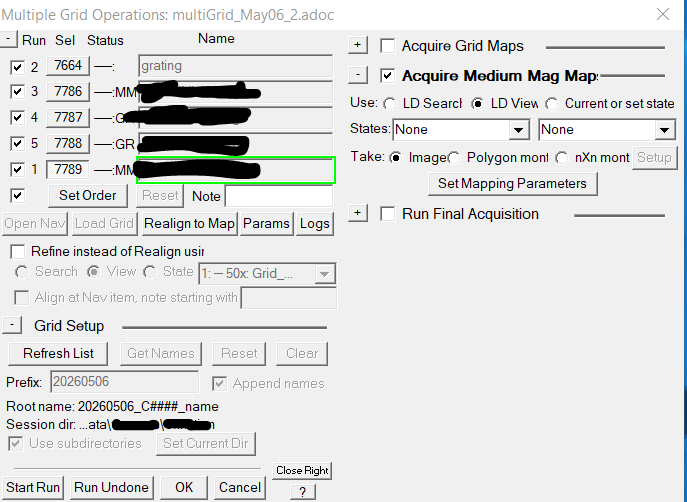
- Click in the Multi Grid Operations Window on "Set Mapping Parameters"
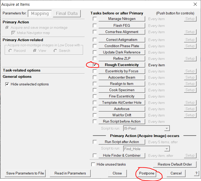
- Make sure that in the newly opened window we have "Rough eucentricity" (Figure 7)
- Click "Postpone".
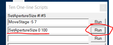
- Insert CL aperture strip 1 by clicking in the Ten One-line Script window on the "Run" command for SetApertureSize 0 100 (Figure 8)
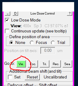
- Go to View mode by clicking "View" in the pink panel (Figure 9).
- Put down the large phosphor screen by clicking "Screen retract" (right hand panel)
- If necessary, center the beam quickly very roughly using the beam shift X and Y buttons (both hand panels), so that some of the center is illuminated. Note: only some part of the middle needs to be illuminated as this is the location of the camera
- Lift up the large phosphor screen by clicking "Screen retract" (right hand panel)
- In the multi grid operation window click "Start run" (Figure 6)
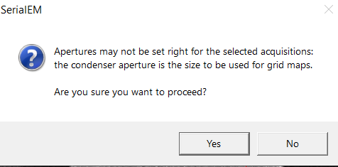
- A pop up message may appear that is asking you if you inserted the proper aperture. If you did insert the 100 um aperture of CL1 click "Yes" (Figure 10).
- Once all squares are done, each square image in the navigator widow has an entry with a label X-A. You can double click on any of the to open the map (Figure 11).
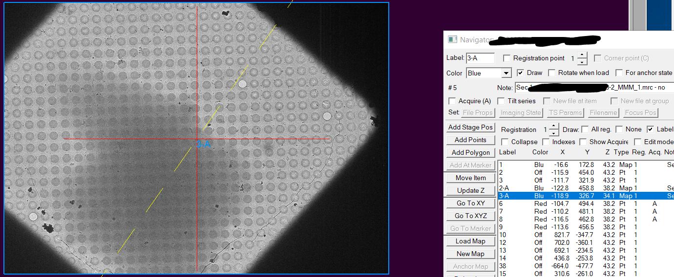
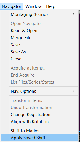
- With One of the map points highlighted (Figure 11), click under Navigator --> Apply saved shift (Figure 12).
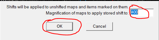
- In the newly opened window the displayed magnification should be 400. Click "OK". Note: If it does not show the right magnification you have the wrong point highlighted in the navigator window (Figure 13).
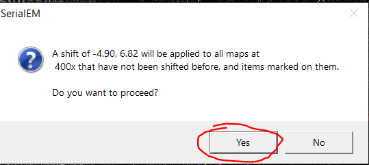
- In the next window click "Yes" to confirm the offset and apply it to all existing 400x maps (Figure 14). Note: This correction is not perfect, but you should be within 1 hole distance.
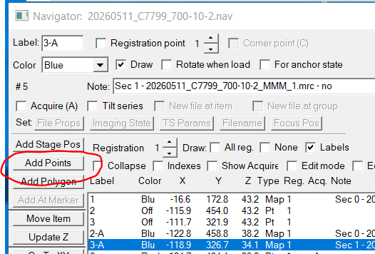
- On the first map add a point for some alignment as well as a point in the hole of interest using the "Add points" button in the navigator window (Figure 15).
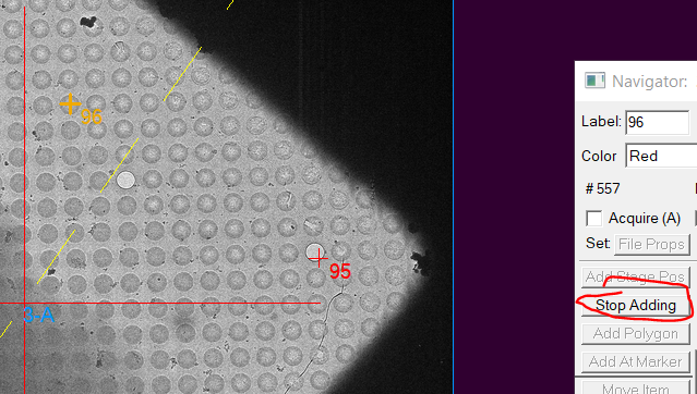
- Click "Stop adding" in the navigator window (Figure 16).
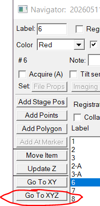
- Highlight with a left click your first point and click "Go To XYZ" in the navigator window (Figure 17)'
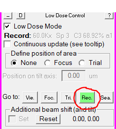
- Go to record beam mode (pink panel, Figure 18).
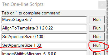
- Insert the small 30 um CL Aperture by clicking "Run" on the One line Script "SetApertureSize 1 30" (Figure 19)
- Put down the large phosphor screen (Right hand panel).
- Make sure that the CL2 30 um aperture is inserted. If not double click on CL2 on the TEM center microscope icon.
- Remove the energy filter slit ("Slit in" button, right hand panel)
- Center the beam using Shift X and Y dials (both hand panels).
- Re-Insert the energy filter slit ("Slit Out" button, right hand panel).
- Adjust "FL focus" right hand panel dial, so that the beam is visible again. At this point it should always be in the counter-clock turning direction. Important: This always happens if you go back and make square images in LM mode. The lenses will return to normal with more time in Mag mode and you have to later turn the FL focus clockwise to keep it aligned;
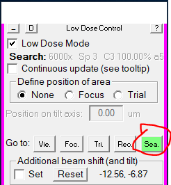
- Go to Search beam mode by slicking "Search" in the pink panel (Figure 20)
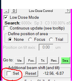
- If the beam is not centered, activate the "Set" checkbox for Additional beam shift (and tilt) in the pink panel (Figure 21).
- Center the beam using Shift X and Y dials (both hand panels).
- Deactivate the "Set" checkbox for Additional beam shift (and tilt) in the pink panel (Figure 21).
- Lift the large phosphor screen (right hand panel, screen Insert)
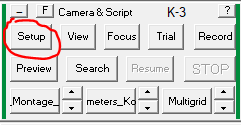
- Open the camera parameters window by clicking Setup in the dark green panel (Figure 22)
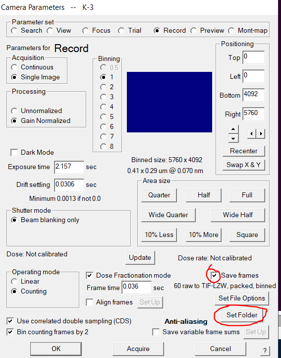
- In the record panel go to "Set folder" (Figure 23). Ensure that "Save frames" is checked. Note: Feel free here to change exposure time and Frame time, but you mostly don't want to.
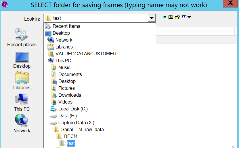
- Select correct record folder for your grid on (X:\Serial_EM_raw_data\myGroup\myName\myGrid\) (Figure 24). Click OK.
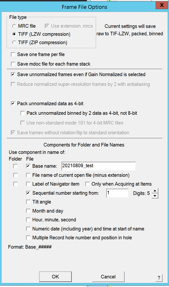
- In the record panel go to "SetFile options" (Figure 25).
- Change your root file name and click "Ok" (Figure 25).
- Back in the setup window confirm all your changes with "OK" (Figure 23)
- Change the parameters of the single hole record by clicking in the Menu bar on Script --> Edit --> 2:Yoneo_test_shots (or similar) (Figure 26).

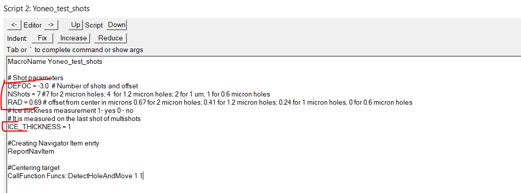
- In the "Yoneo_test_shots" script you can adjust the defocus value (DEFOC). the number of shots around the center (NShots), the radius around the center (RAD) and if you want to measure ice thickness (Figure 27). Confirm with "OK". Note: Maximum shot values for 2um holes is 7 shots, 0.69 rad; 1.2 um holes is 4 shots; 0.41 rad; 0.6 um holes 1 shot, 0 rad.
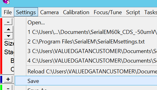
- For safety reason in case of crashes save the setting via the Menu bar Settings --> Save (Figure 28).
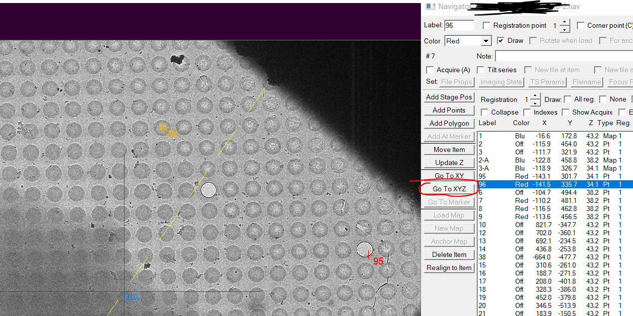
- Highlight the hole target item of interest in the navigator window and click "Go to XYZ" (Figure 29).
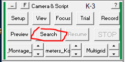
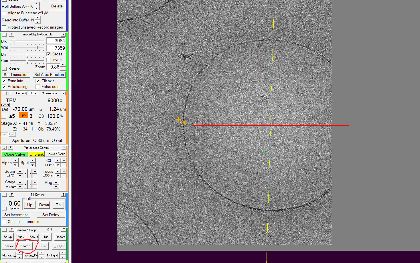
- Make a Search image by clicking "Search" in the dark green camera panel (Figure 30).
- Check that the background job is running in the terminal window (Figure 31).

- If the job would not be running or the terminal is closed, open a terminal and go to the proper folder using cd (Figure 32) and start the bat script of Yoneo (Figure 32).

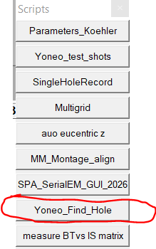
- In the Scripts panel click on Yoneo_find_hole (Figure 33) Note: This script is superior to the FindAndCenterHole command in the alternative option (bottom of SOP) in almost all tested cases (many large linear structures could interfere most)
- After the hole is centered make another Search image (Figure 34).
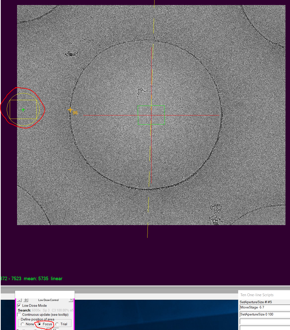
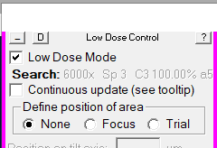
- In the pink panel activate "Focus" under "Define position of area" and make a left click on the image where you want to do the focus on the carbon area (Figure 35).
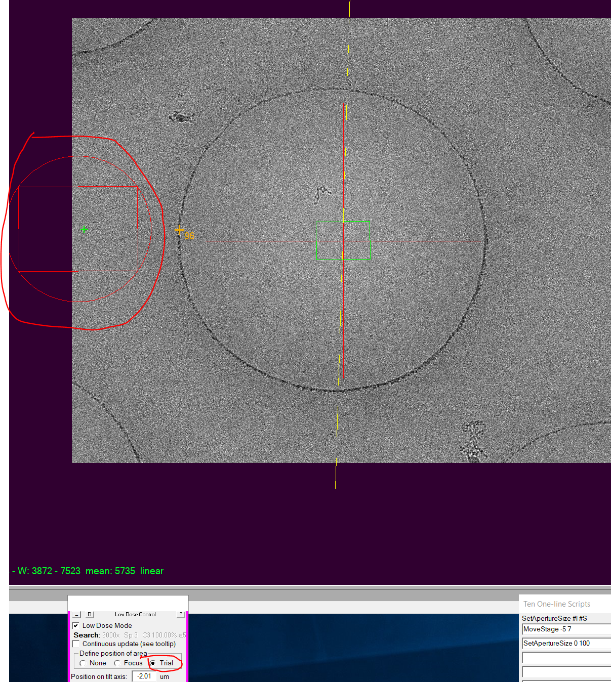
- In the pink panel activate "Trial" under "Define position of area" and make a left click on the image where you want to do the beam centering on the carbon area (Figure 36).
- In the pink panel activate "None" under "Define position of area" (Figure 37).
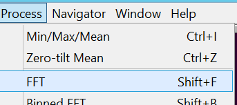
- If you do not see the FFT panel it is recommended to open it now via the Menu bar Process --> FFT (Figure 38)
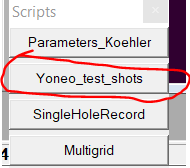
- In the script panel click on "SingleHoleRecord" to do the test shots (Figure 39). Important: If the hole is centered in view mode but the record images hit the carbon area, you need to do a search vs record alignment!
- Repeat Add point, Go to XYZ, Yoneo_test_shots (last step) on multiple places on the grid until you know if you have a good grid for data collection or not. Note: You do NOT need to make an additional Search images after Go to XYZ
- When finished with test shots, save the navigator file (Navigator --> Save).
- Repeat the whole procedure for all other grids you want to test shoot. Note: Don't forget to change then the folder location and the position of focus and trial mode.
Square imaging (Multi-Grid)
At this point you have figured out which grid you want to use for automated data collection over night. If you want you can set up square images for multiple grids, to be done automatically sequentially.
- Open Navigator by selecting the ID of your grid of interest in the Multi-Grid window and click on "Open Nav" (Figure 1)
- In the navigator window double click on the item corresponding to your atlas. It is a "Blu" colour item with the label 1 (Figure 2).
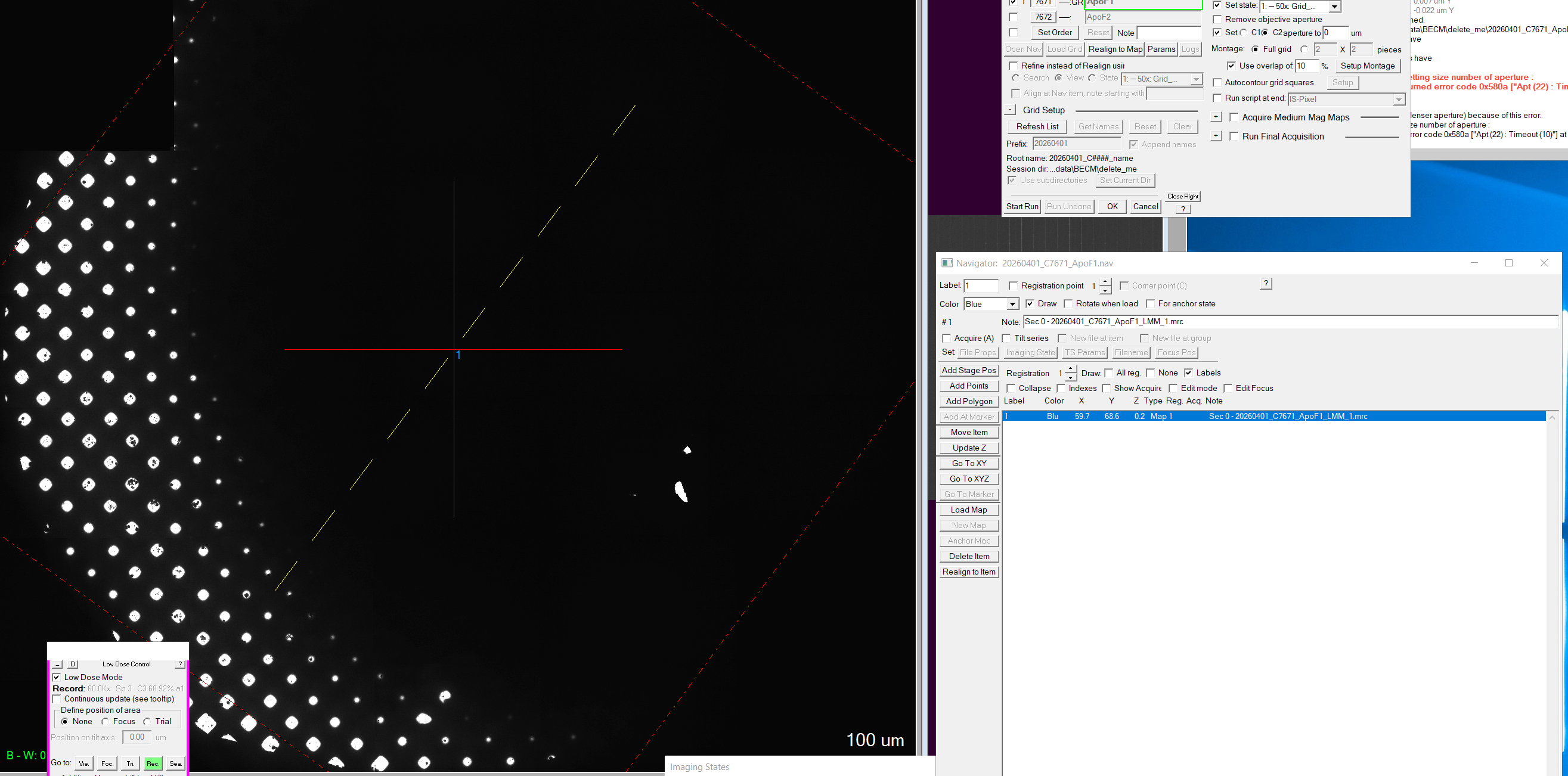
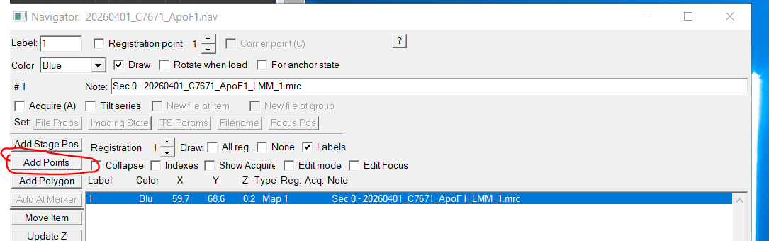
- In order to select targets for square montages, click in the navigator panel on "add points" (Figure 3). Then left click on suitable squares creating a red cross per item (Note: you can zoom in and out which your mouse wheel, holding left mouse click and dragging will allow you to move through the image)
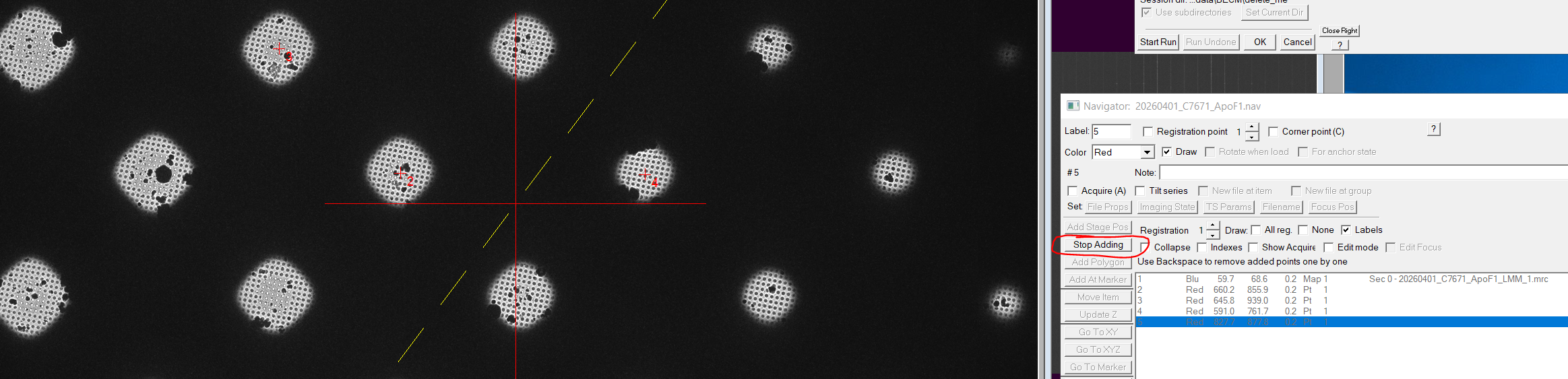
- Once all suitable squares are selected clock "Stop Adding" in the navigator window (Figure 4). (Note: You can repeat this procedure for every grid on which you'd like to make square images)
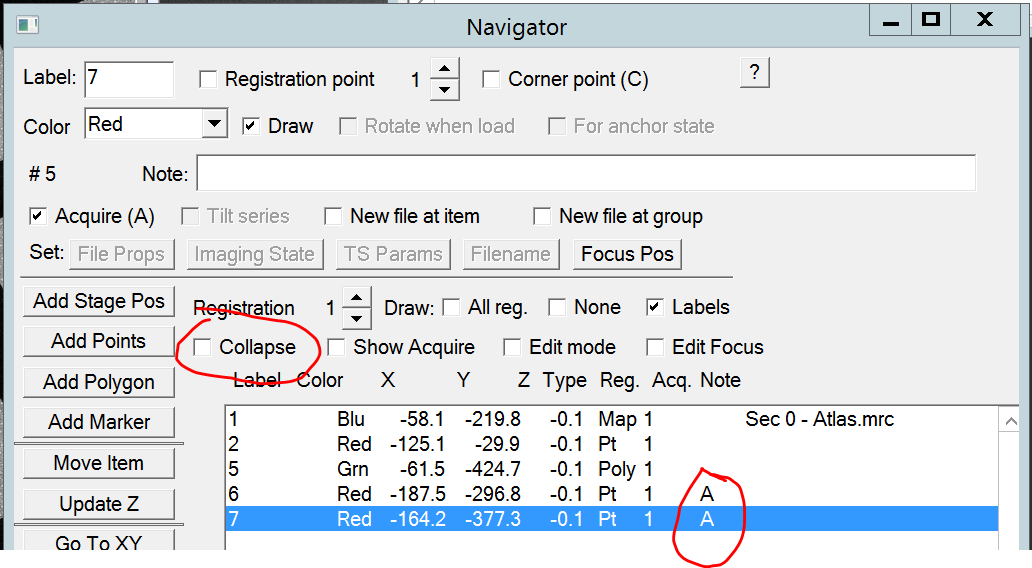
- All square targets need to be set for acquisition. For this click on "collapse" to collapse targets into a group and on the keyboard click "A". Once you uncollapse again you see all targets marked with an A (Or the group as All Acquire) (Figure 5)
- In the Multi Grid operations window select all grids on which you have prepared square targets and that you would like to collect montages on (Figure 6). Note: It is enough if only one grid is selected.
- In the Multi Grid Operations window you should still have "Acquire Medium Mag Map" procedure active from the test shots (Figure 6)
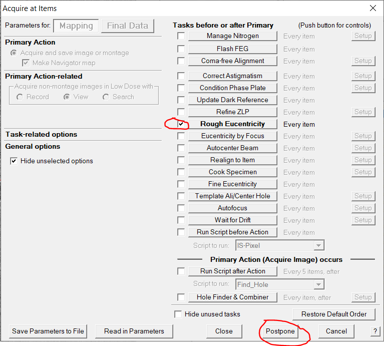
- Optional: You can check again "Set Mapping Parameters" (Figure 6) and you should still have the same parameters active as during the test shot procedure (Figure 7). Click "Postpone".
- Insert CL aperture strip 1 by clicking in the Ten One-line Script window on the "Run" command for SetApertureSize 0 100 (Figure 8)
- Go to View mode by clicking "View" in the pink panel (Figure 9).
- Put down the large phosphor screen by clicking "Screen retract" (right hand panel)
- If necessary, center the beam quickly very roughly using the beam shift X and Y buttons (both hand panels), so that some of the center is illuminated. Note: only some part of the middle needs to be illuminated as this is the location of the camera
- Lift up the large phosphor screen by clicking "Screen retract" (right hand panel)
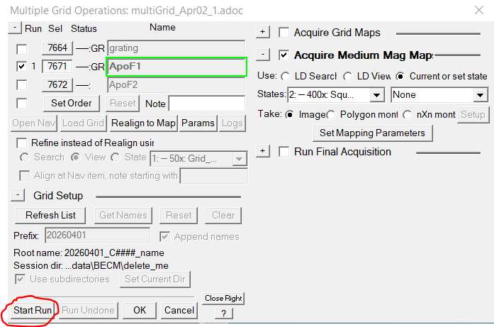
- In the multi grid operation window click "Start run" (Figure 6)
- Back in the Multi Grid operations window click "Start Run" to do the Square mapping (Figure 10).
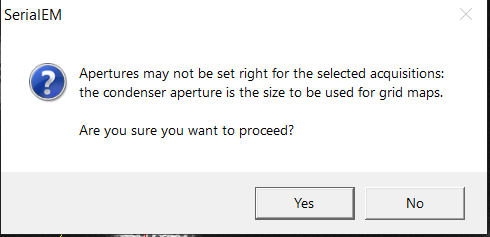
- A pop up message may appear that is asking you if you inserted the proper aperture. If you did insert the 100 um aperture of CL1 click "Yes" (Figure 11).
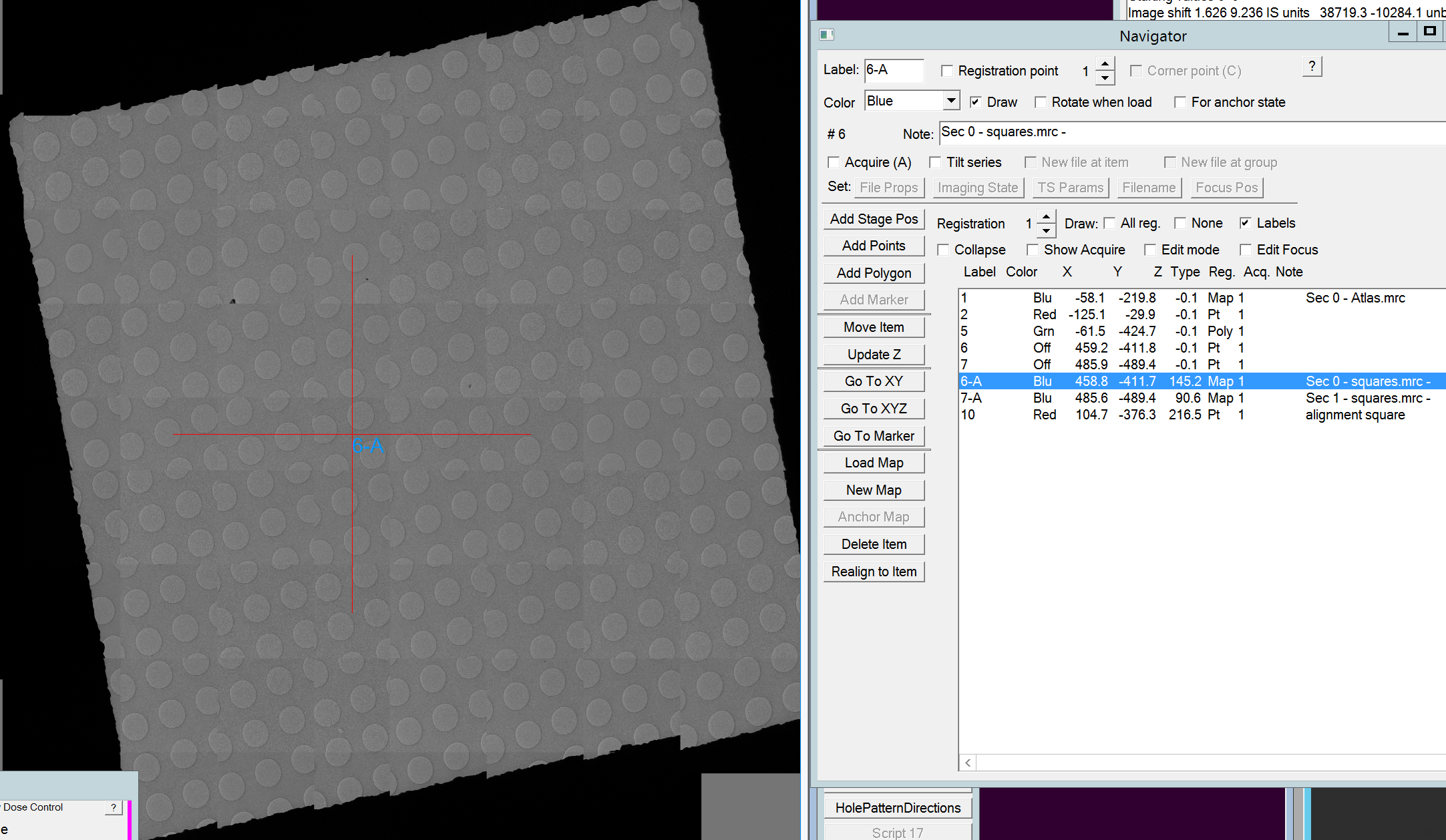
- Once all squares are done, each square image in the navigator widow has an entry with a label X-A. You can double click on any of the to open the map (Figure 12).
- With one of the new square map points highlighted, click under Navigator --> Apply saved shift (Figure 13)
- In the newly opened window the displayed magnification should be 400. Click "OK". Note: If it does not show the right magnification you have the wrong point highlighted in the navigator window (Figure 14).
- In the next window click "Yes" to confirm the offset and apply it to all existing 400x maps (Figure 15). Note: This correction is not perfect, but you should be within 1 hole distance at this point.
- Go to record beam mode (pink panel, Figure 16).
Finding and combining holes and grabbing the hole pattern
Finding holes
- Open the acquired square image by double clicking in the navigator window onto the line of your square ( XXX-A; Blue point; named Map; comment SecX - squares.mrc) (Figure 1).
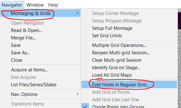
- In the Menu bar select Navigator --> Montaging & Grids --> Find holes in regular grid... (Figure 2).
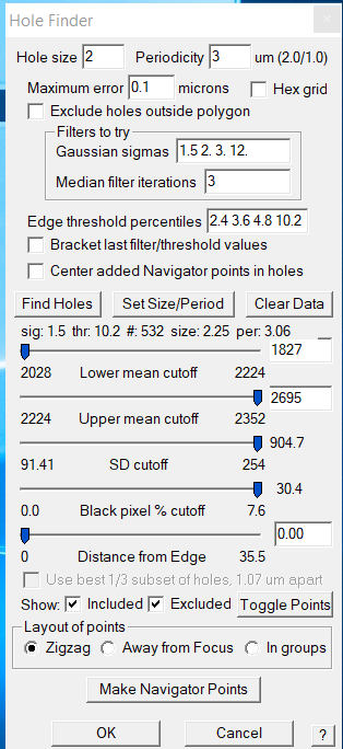
- In the new Hole Finder window specify the hole size of your grid and the periodicity (Figure 3). Note: periodicity is hole size plus distance between holes! Note 2: If your grid hole sizes differ from manufacturer specification you can measure the distances in the view image or square montage by holding the shift button on the keyboard and clicking & dragging the left mouse button on the image.
- The maximum error may need some adjustment and should be changed in a manner that it maximizes picking coverage and accuracy. (I use usually 0.1 um error).
- Click the "Find holes" button (Figure 3).
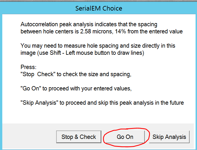
- SerialEM may display a choice dialogue (Figure 4). Click "Skip Analysis" to proceed. Note: Out of experience the autocorrelation peak is always worse than your entered parameters.
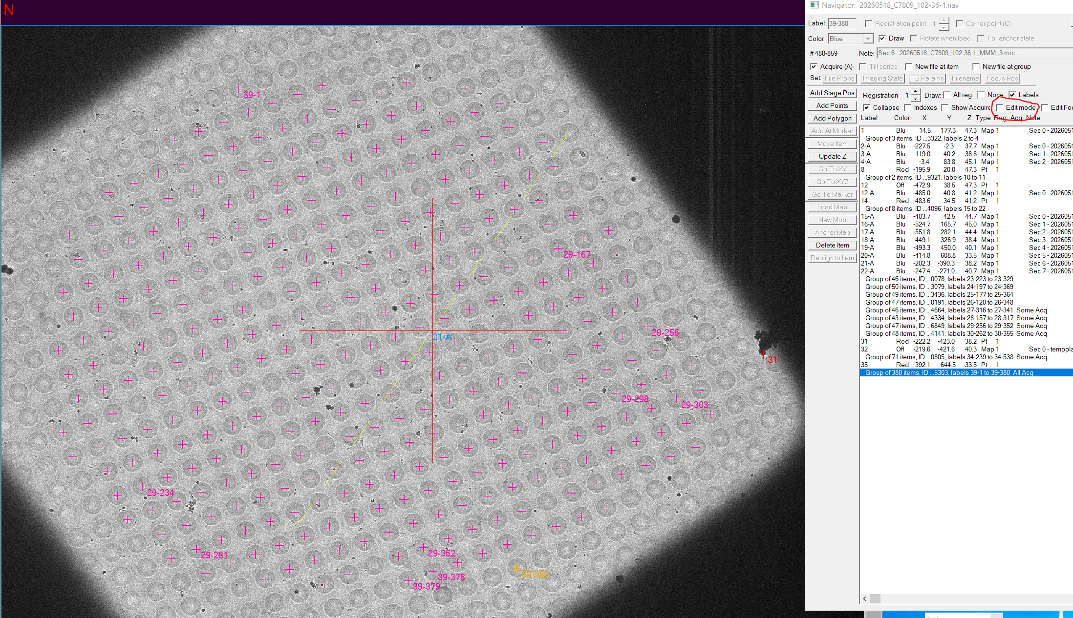
- SerialEM will display all picked holes with a cross. Change the input parameters and click find hole again, if you do not like the picking. Note: The goal is to maximizes picking coverage and accuracy. Smetimes the actual hole size is different from the stated size on your box. You can measure distance in the picture by holding Shift, left clikcing on the start of the measuriment and dragging until the end. The distance is shown is in the log file
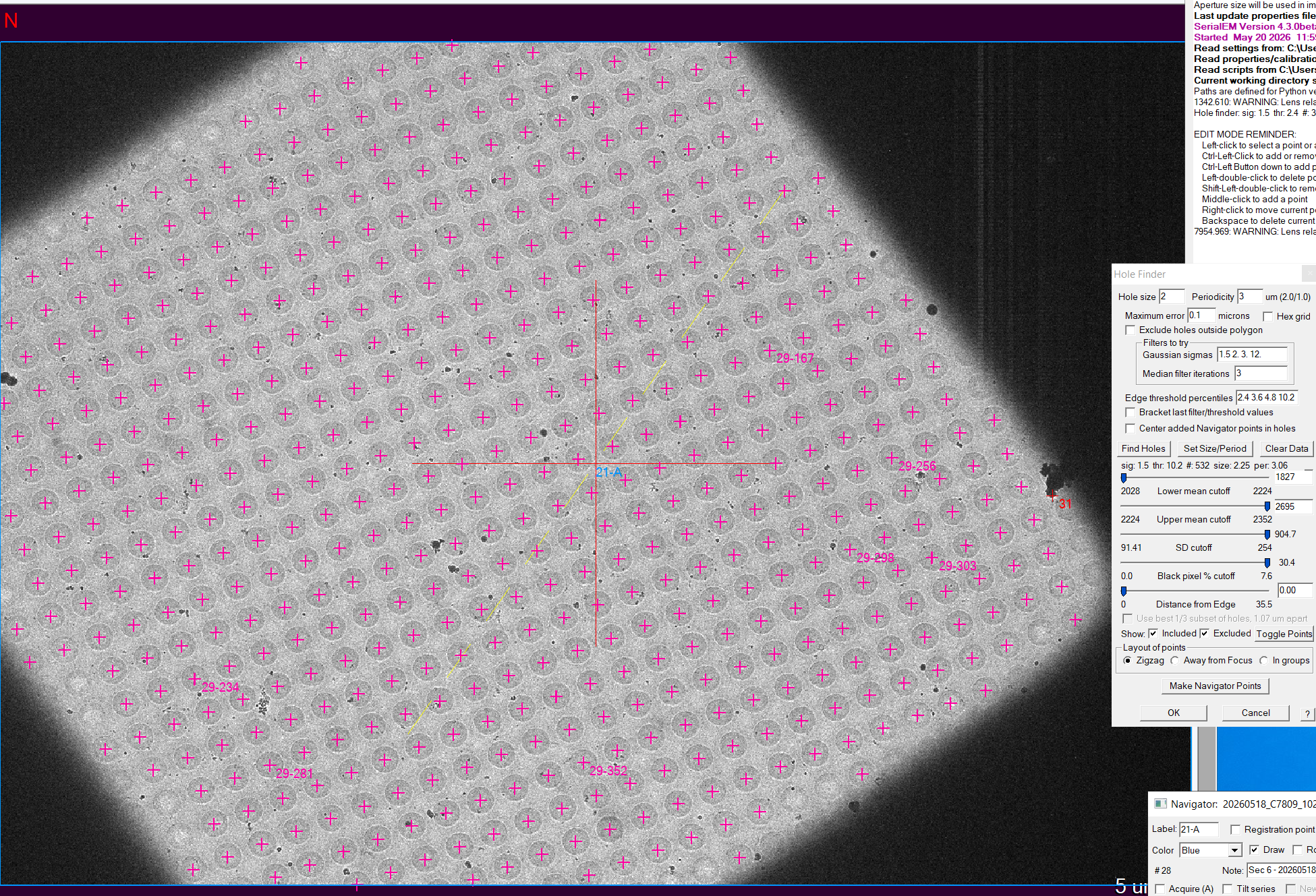
- You can change the five sliders to adjust which holes should be included (pink) or excluded (blue/cyan) for data acquisition (Figure 6). Note: I mainly focus on distance from edge to avoid the crystalline ice there and maybe SD cutoff to get rid of contaminant holes
- Once you are happy with the results, click the "Make Navigator Points" button (Figure 6).
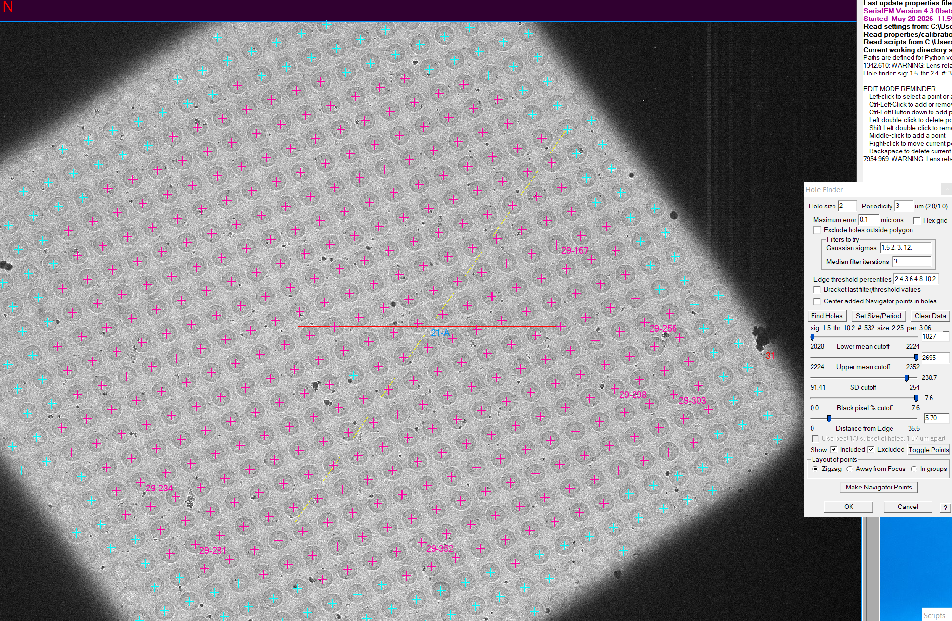
- Now you can still manually delete and add targets. For this activate "Edit mode" on the navigator window (Figure 7). Left click on an item will select the item and backspace (keyboard) can delete that item. Right click will move the currently selected item. Middle mouse click will add an item to the group.
- Once you are done the square picking might look like Figure 7.
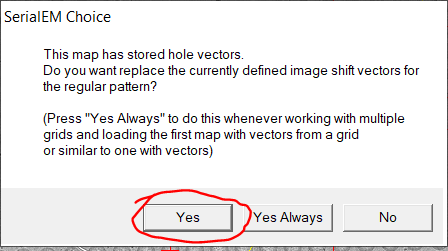
- Repeat the picking for all squares. Important: When double clicking on the second square a message box appears (Figure 8). Click on "Yes" to use the hole pattern you just found at 400x magnification.
Combining holes
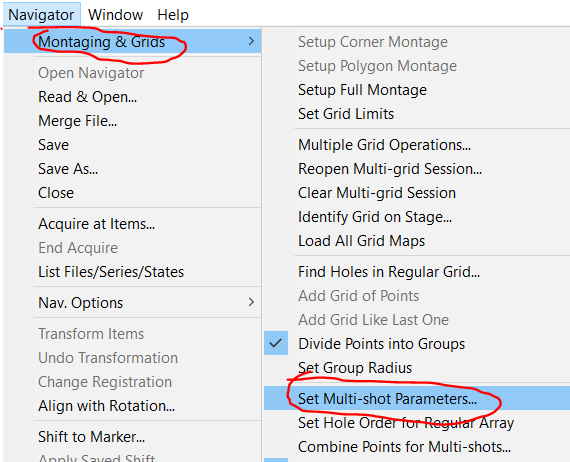
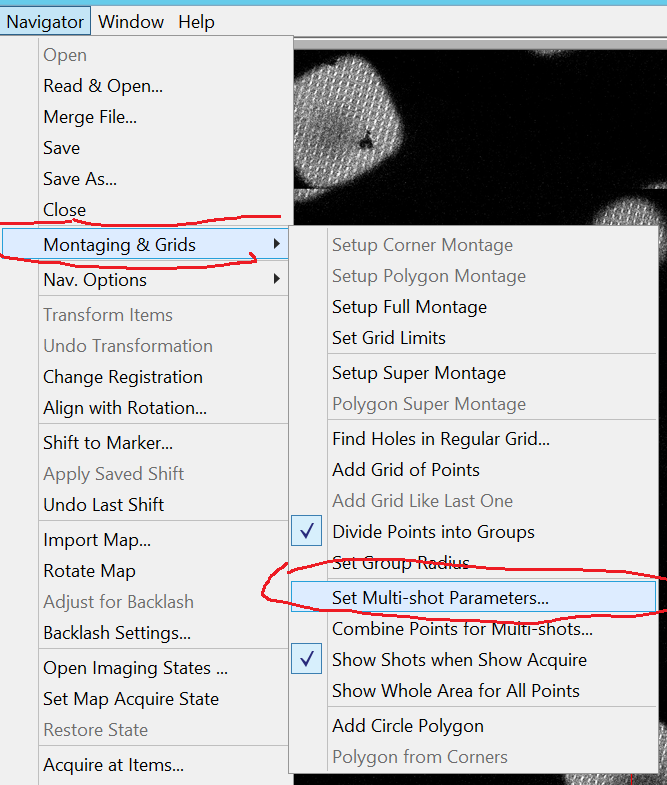
- In the menu click on Navigator --> Montaging & Grids --> Set Multi-Shot Parameters (Figure 9)
- In the multi shot dialogue make sure the proper "regular array of holes" is selected: 3x3 for 2/1 holes and up to 5x5 for 1.2/1.3 and 0.6/1 holes. Click ok (Figure 10).
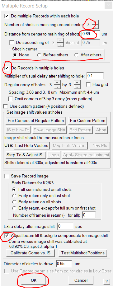
- You now want to combine the holes into acquisition targets for multi hole collection.
- In the Menu bar click on Navigator --> Montaging & Grids --> Combine Points for Multi-shots (Figure 11).
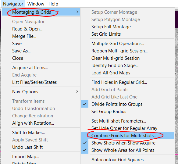
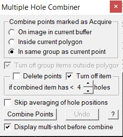
- Make sure that you have selected any point "in same group as current point" of items you want to combine for multi-shot and click in the Multiple Hole Combiner window the "Combine Points" button (Figure 12).
- Select "Turn off Items" that are less than X holes. Note: To increase throughput you want a high number, to increase coverage you want a small number. In general I use less than 3 or 4 items (Figure 12).
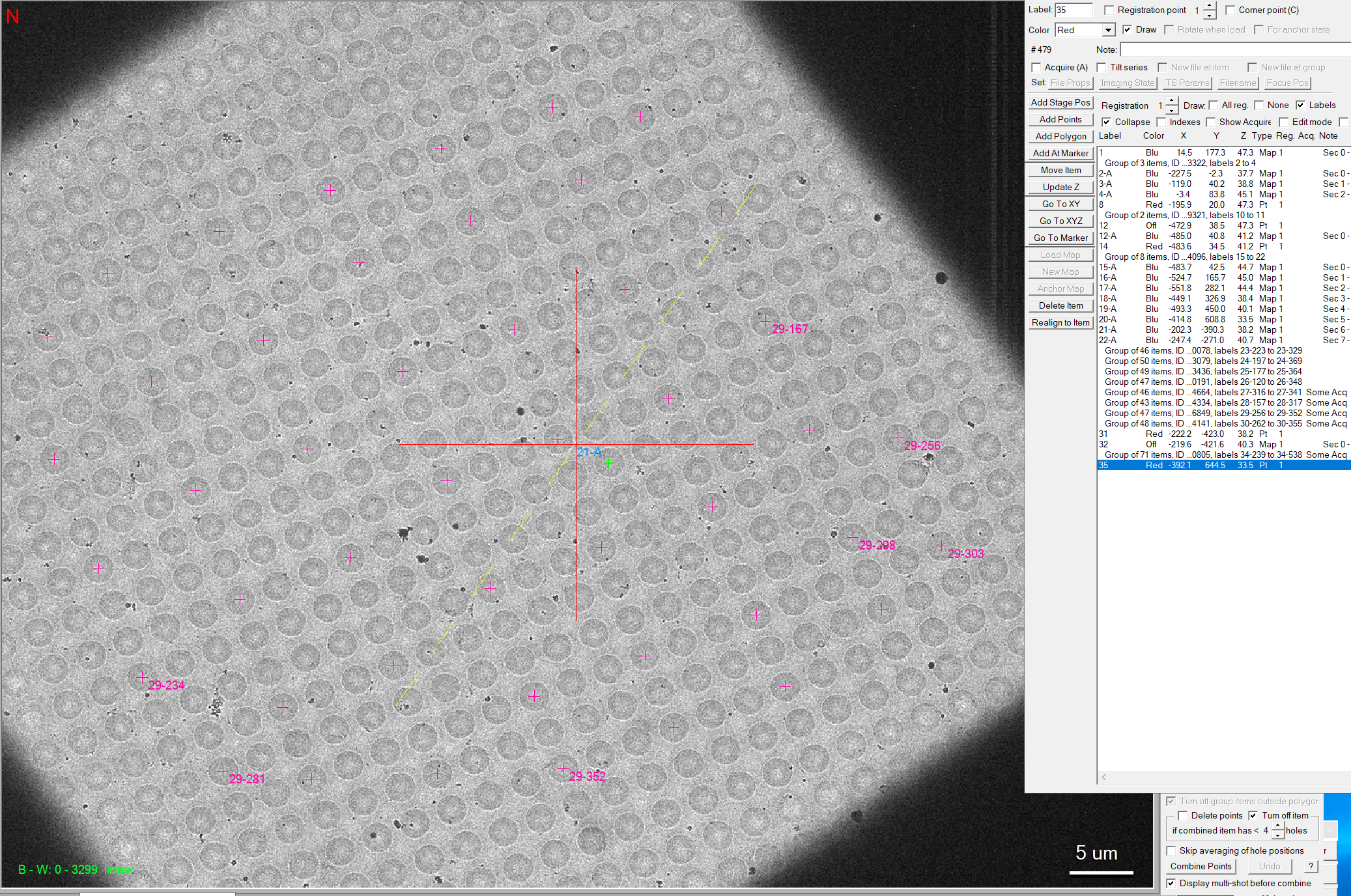
- The list of single items will be gone from the navigator window and is replaced with the Multi-hole shot items (Figure 13)
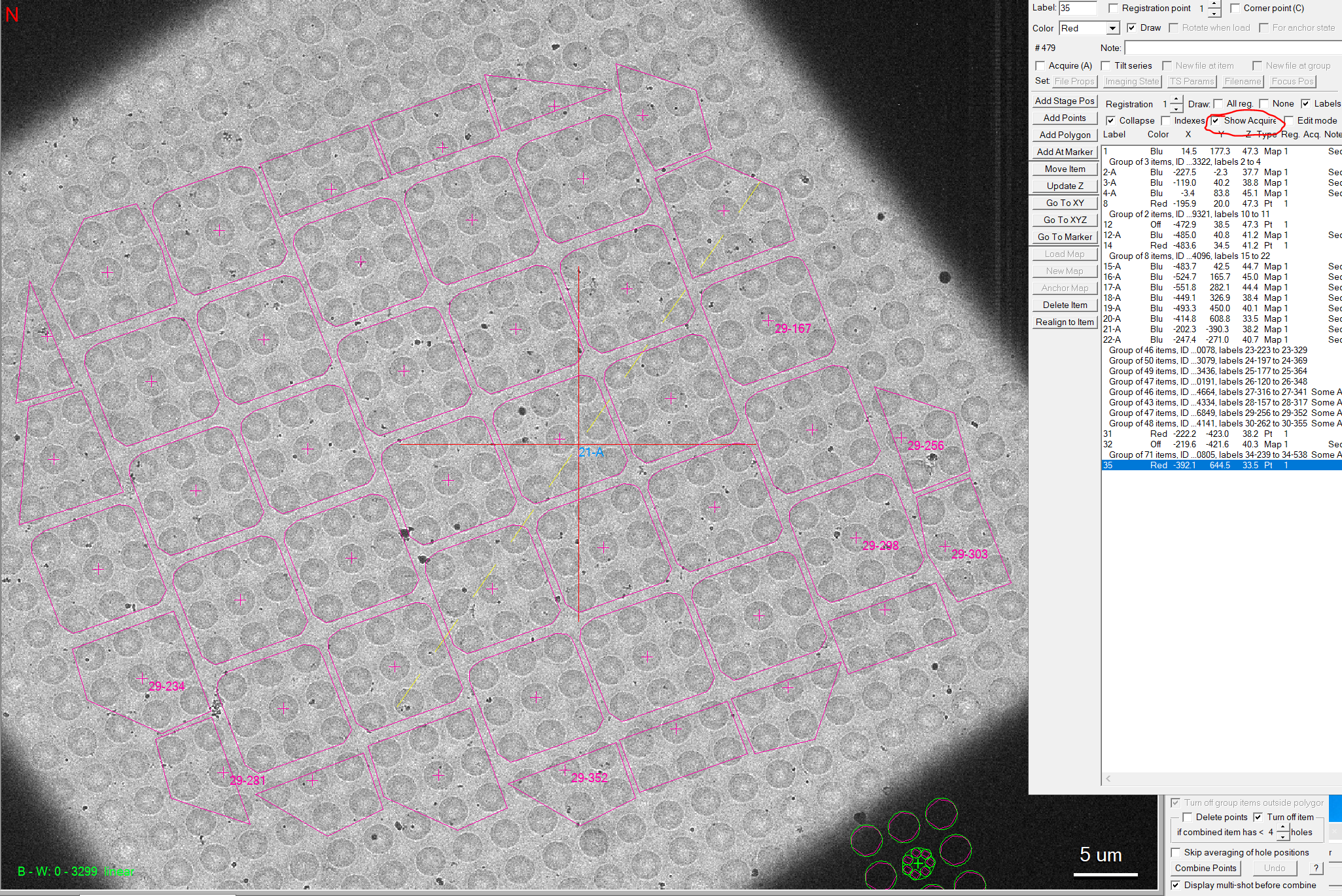
- Optional: You can display which and how many holes are shot for each item if you activate the "show acquire" checkbox in the navigator window and select any of the acquisition targets therein (Figure 14).
- Repeat hole combining for all your squares. Hint: If you selected the targets of the first square for your first hole combining, you can just keep on clicking "Combine Points" until you reached the last one automatically as the combine items get pushed to the bottom of the list.
Hole pattern
- We now need to grab and/or adjust the hole pattern from your hole picker on the square.
- Open the Multi Shot parameters dialogue via "Navigator --> Montaging & Grids --> Set Multi-Shot Parameters" (Figure 15)
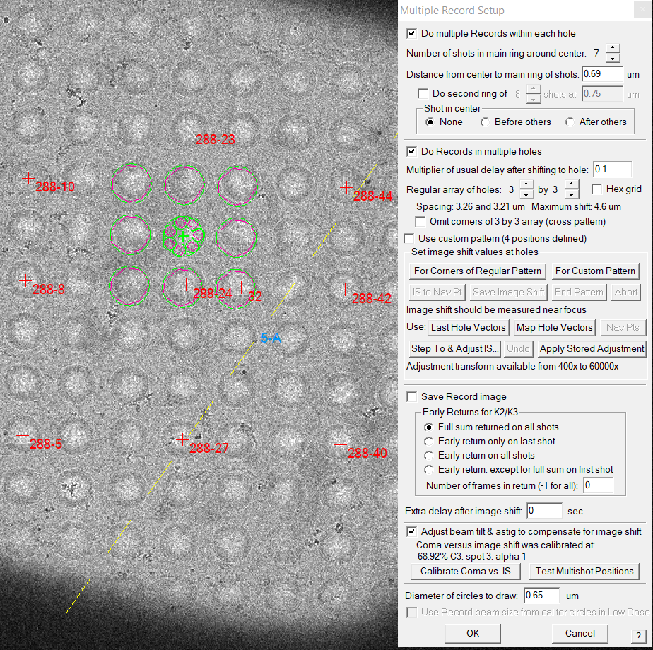
- If you make a left click on the loaded square you can see the current hole pattern (Figure 16). Note: The circles for the multi shot holes are green.
- If it does not show your hole pattern, you can click on "Map hole vectors" to grab them from your current map (Figure 16)
- Adjust the pattern by clicking "Apply Stored Adjustment"
- You can now see on the square the adjusted pattern. The yellow colour of the circle shows you that the adjustment was applied (Figure 17) Note: It will never look perfect because of calibration offsets towards the view mode magnification. So the seen offset is correct.
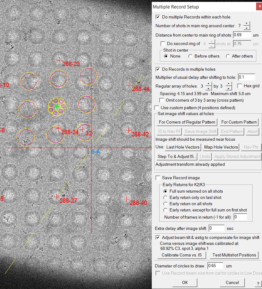
- Click the "OK" button to close the Multiple Record Setup dialogue.
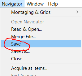
- For safety reason in case of crashes save the Navigator via the Menu bar Navigator --> Save (Figure 18).
- For safety reason in case of crashes save the settings via the Menu bar Settings --> Save (Figure 19).
CL Stigmator correction
- Go to record mode (pink panel) (Figure 1).
- Put down the large phosphor screen (screen retract, right hand panel)
- Condense the record beam to a small spot using the brightness dial (left hand panel, counter-clockwise)
- Roughly center the beam using Shift X&Y (both hand panels)
- Insert the focus screen (FScreen retract, right hand panel)
- Roughly center the beam using Shift X&Y (both hand panels)
- If the beam is not circular, assign CL Stigmators to the Def/Stig knobs (CL Stig, left hand panel, will light up). Otherwise you do not need to do this correction.
- Use Def/Stig X&Y knobs to make the beam circular
- Once finished un-assign CL Stigmators by clicking CL Stig (left hand panel)
Coma free alignment
Make sure you do not have residual drift during the procedure as this will harm the results.
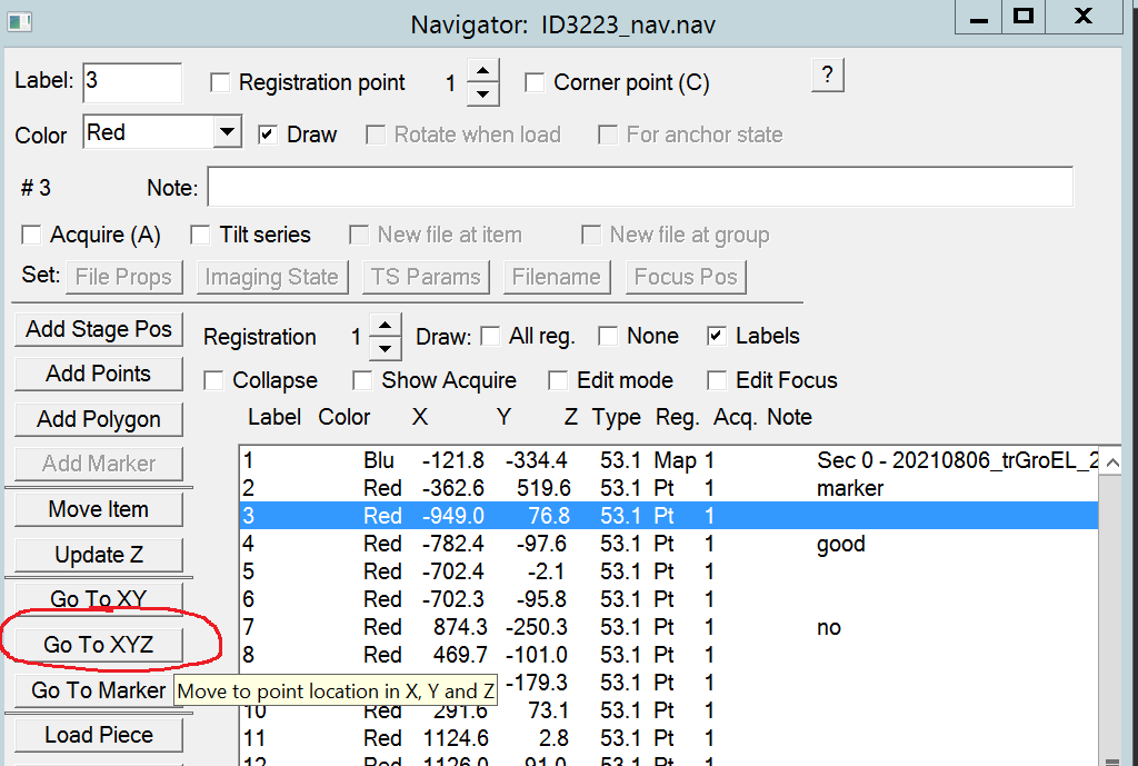
- If not there yet, go to your alignment square by highlight the point corresponding to your alignment square and click on Go to XYZ (Figure 1).
- Important: Make sure that you are actually at eucentric height. (I.e go to record mode, hit std focus, measure defocus and manually adjust z-height with the small hand panel on the left). Often This should have already more or less the proper z-height due to procedures before.
- Put down the large phosphor screen (Screen retract, right hand panel).
- Hit Standard Focus (STD Focus, right hand panel).
- Move the stage with the track ball over the carbon area.
- Center beam with Shift X&Y both hand panels.
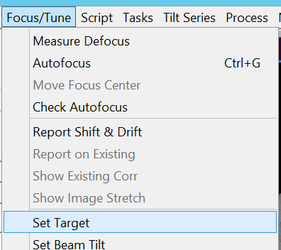
- Define a target defocus by clicking in the SerialEM Menu bar on Focus/Tune --> Set Target (Figure 2).
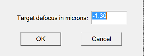
- Set the target to -1.3 um defocus (Figure 3).
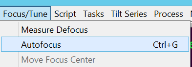
- In the Menu bar go to Focus/Tune --> Autofocus to do auto-focusing (Figure 4). Hint: If the focus position ends up in the hole and focusing fails, you may want to temporarily set "Define position of area -- Focus" to 0 um offset. Undo this before starting the data collection.
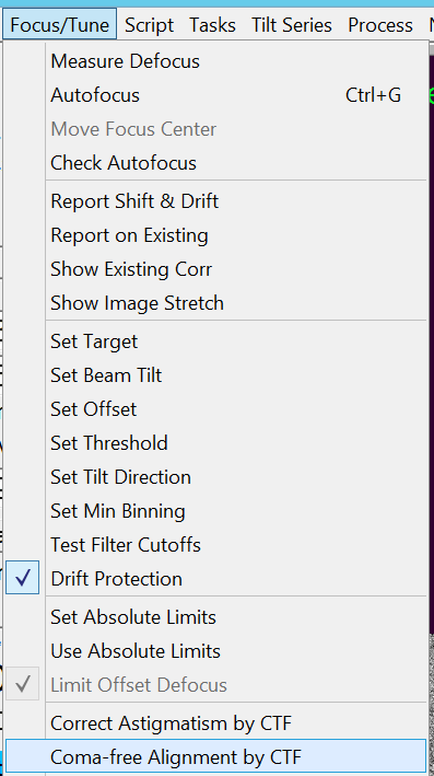
- Do coma free alignment by clicking in the Menu bar on "Focus/Tune --> Coma-free alignment by CTF" (Figure 5). Important: Check in the FFT image that the fit (yellow dashed lines) corresponds to measured location of Thon rings.
- The log file reports the amount of beam tilt correction (Figure 6). Hint: High score and low fit to values indicate a good run.

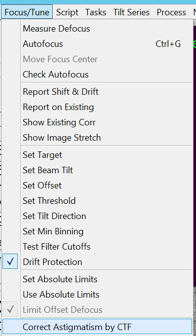
- Do astigmatism correction by clicking in the Menu bar on "Focus/Tune --> Coma astigmatism by CTF" (Figure 7).
- The log file reports the amount of OL stigmator correction (Figure 8). Hint: High score and low fit to values indicate a good run.

- Repeat steps 9-12 until stable. Sometimes you do 2 or 3 cycles. Important: Long term Search mode affects the beam tilt temporarily. Try not to do it directly square imaging and make sure you have been for some time in record mode
- This can be repeated after 1 h of running data collection if your beam tilt is not yet stable/
Search vs Record alignment
I assume here that you are still on your alignment square you used to do coma free alignment
- Ensure you are in record mode (Figure 1)
- Ensure that there is no IS currently applied to the microscope (orange panel) (Figure 2)
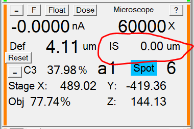
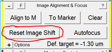
- If there is an Image shift reset image shift (yellow panel) (Figure 3). If not, continue to next step.
- Put down the large phosphor screen (screen retract, right hand panel).
- Minimize the beam using the brightness dial (left hand panel) and wait a few seconds to burn a hole in the ice. Important: If this area is already completely burned or free of ice, move the stage with the trackball to a fresh area.
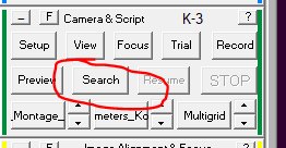
- Make a single search image with SerialEM (dark green panel, Search) (Figure 4).
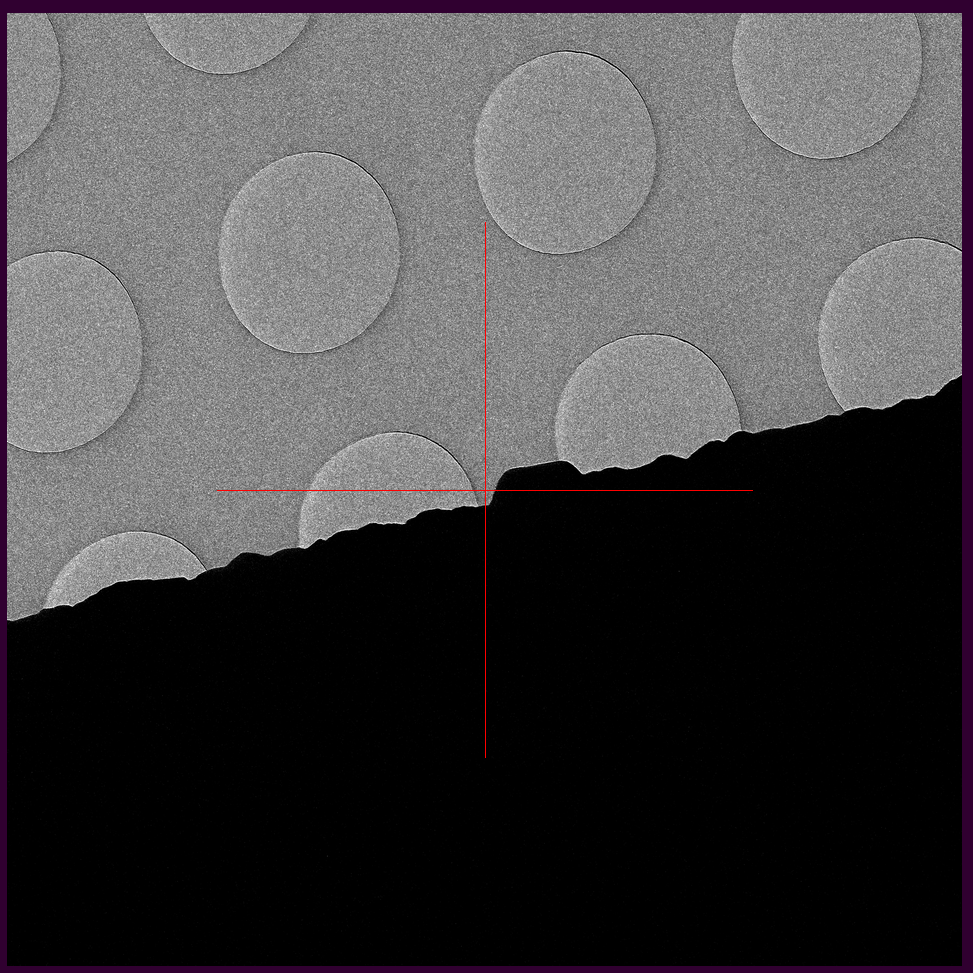
- If there is a mis-alignment between Search and Record mode (i.e. because you adjusted the beam tilt) you will see the burned hole in the ice off centered (Figure 5). (Note: Here I used a pre-existing feature)
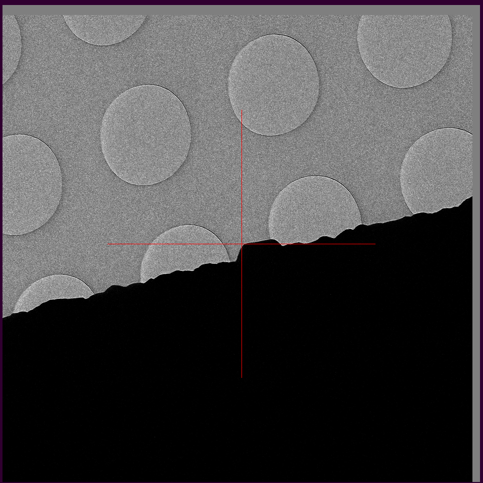
- Keep the right mouse button pushed on the image in SerialEM and drag the burned ice feature to the center (indicated with a giant red cross) (Figure 6). (Note: Here I used a pre-existing feature)
- Confirm the offset in the pink panel by clicking "Set" under "Offset for Search" (Figure 7).
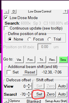
- SerialEM will make a new image with the burned ice hole feature now centered (and no grey bars) (Figure 8). (Note: Here I used a pre-existing feature)

- Go back in Record mode (pink panel, rec) (Figure 9).
- Put down the large phosphor screen (screen retract, right hand panel).
- Confirm that the burned ice feature is still centered on the phosphor screen. If not, redo the procedure.
Starting up data collection
Centering CL aperture
- Go to record mode (Figure 1).
- Put down large phosphor screen (screen retract, right hand panel).
- minimize the beam with the brightness dial (left hand panel, counter clockwise) (Figure 2).
- Center beam with Shift X&Y (both hand panel) (Figure 2).
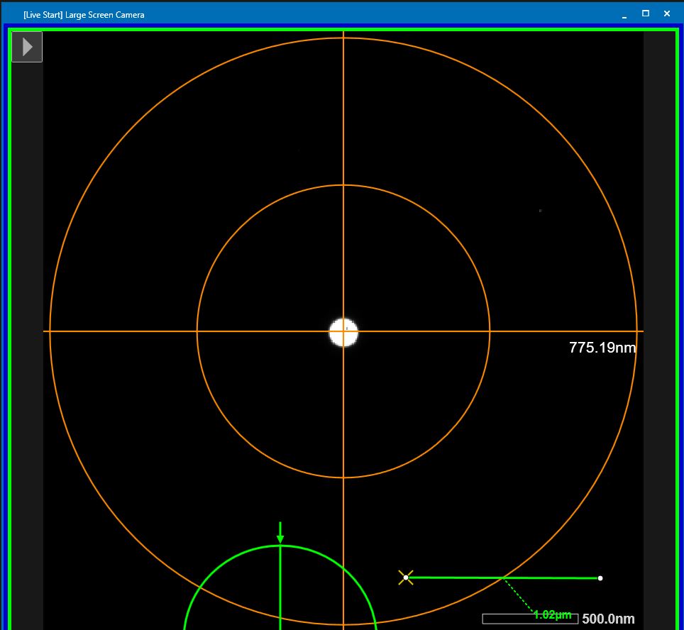
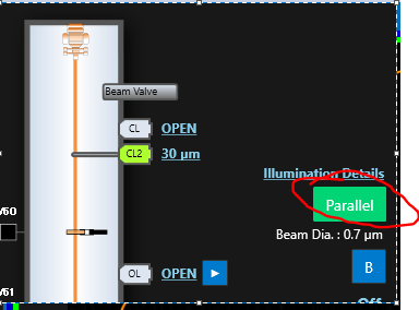
- Spread the beam until more or less the size of the green ring (brightness dial, clockwise, left hand panel) (Figure 3) or by clicking on "parallel" in the TEM center next top the microscope pictogram (Figure 4) Note: If you do not see the neither a orange or green circle, right click on the large screen camera image --> Show circle scale
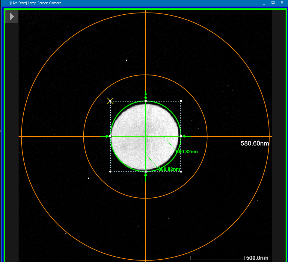
- If the beam is off-centers now, move the position of the CL aperture until the beam appears centers again by hovering over the CL2 aperture size value and use the arrows to move it (Figure 5).
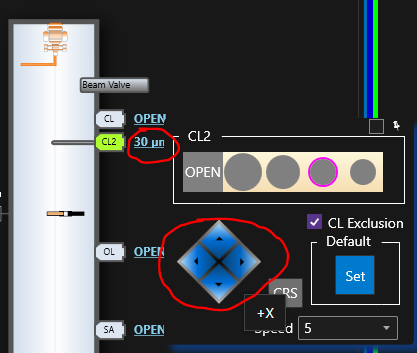
- The beam should now be centered again, indicating a centered CL aperture (Figure 6).
Aligning beam shift for different illumination modes
- Go to record mode (Figure 7). Note: This also restores the brightness value which was changed in the last procedure.
- Put down large phosphor screen (screen retract, right hand panel).
- Center beam using shift X&Y (both hand panels).
- Go to Search mode (Figure 8).
- Activate the check box "Set" under "additional beam shift (and tilt)" (pink panel) (Figure 9)
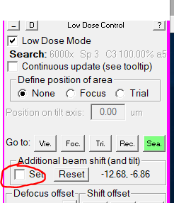
- Center beam using shift X&Y (both hand panels).
- Un-check the previous box "Set" under "additional beam shift (and tilt)" (pink panel) (Figure 9). Note: Every time you adjust beam tilt in record and do a search vs record alignment, you only need to change the beam shift offset between record and search and you can skip focus and trial.
- Go to focus mode ("Foc.", pink panel) (Figure 10).
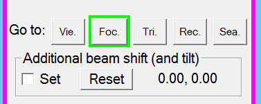
- Note: The beam is expected to be centered. Hit "reset" under "additional beam shift" if the values are not zero.
- Recenter the beam using shift X&Y (both hand panels). Note: The only reason the beam moved was lens hysteresis. You do not see this movement if you switch directly between Record and Focus mode.
- Go to trial mode ("Tri.", pink panel) (Figure 11).

- Activate the check box "Set" under "additional beam shift (and tilt)" (pink panel) (Figure 12)
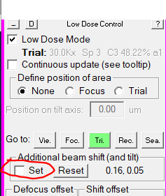
- Center beam using shift X&Y (both hand panels). Note: An accurate relative center between trial and record is very important as this ensures a centered beam during data collection.
- Un-check the previous box "Set" under "additional beam shift (and tilt)" (pink panel) (Figure 12)
- Go to record mode (Figure 13).
- Note you may need to cycle again through Rec. --> Foc --> Tri. in case the beam is not stable yet
Confirm camera parameters
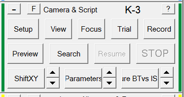
- Open Camera Setup (dark green panel, Setup) (Figure 14).
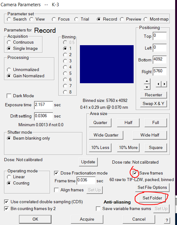
- In the record panel (Figure 15) ensure that "Save frames" is checked. Click on "Set Folder". Note: Feel free here to change exposure time and Frame time, but you mostly don't want to. we have it set to give you approx. 1 e-/A2/frame and 60 e-/A2 total dose
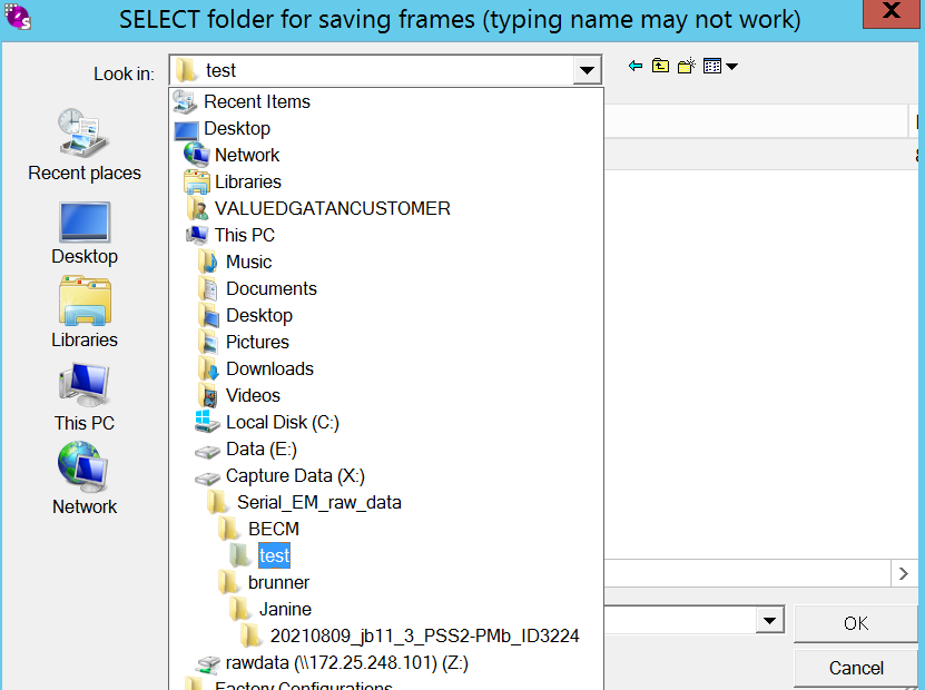
- Ensure that you are in the correct record folder on (X:) and use the folder corresponding to your current grid (Figure 16). Click OK.
- In the record panel go to "SetFile options" (Figure 15).
- Change your root file name to a proper name. This will be the name of your final data. Click "Ok" (Figure 17).
- Back in the setup window confirm all your changes with "OK" (Figure 15).
Optional: Create target reference (Only needed if you do NOT use the AI hole targeting that is the standard)
- At this point I assume that you are still on the alignment square and at eucentric height.
- Put down the large phosphor screen (Screen retract, right hand panel)
- Go to search mode (pink panel, search) (Figure 18).
- Move the stage roughly to a clean hole with nice thin ice or even no ice. You want to avoid areas with large ice contaminants as they can affect the hole targeting.
- Make a Search image by clicking "Search" in the dark green camera panel (Figure 19).
- The camera will make an image at 6k magnification. In the ten-One line script window the command "FindAndCenterOneHole" should still reflect your hole size. If not, adjust it. (Figure 20)

- Click "Run" on that command to center the hole (Figure 21).
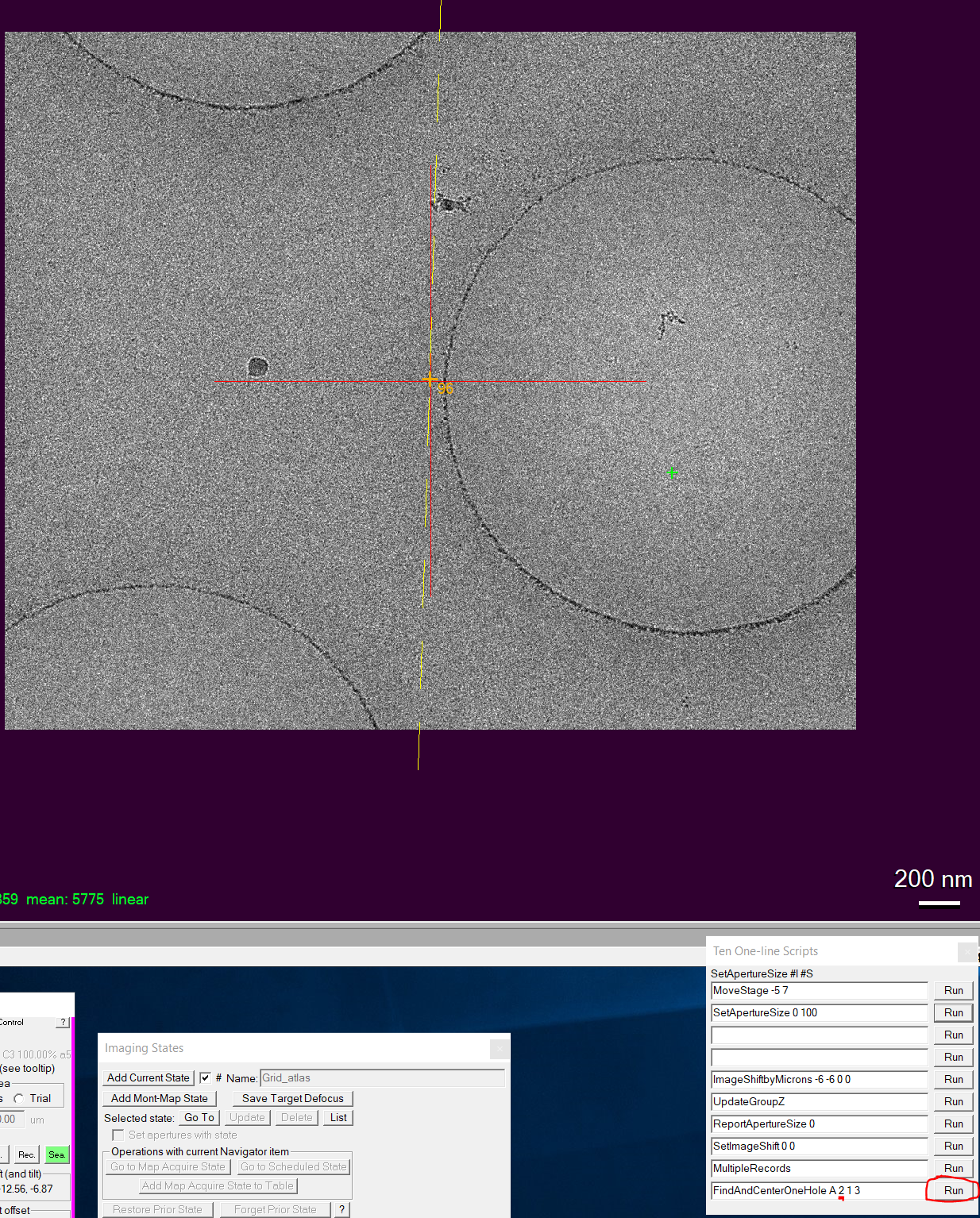
- After the hole is centered make another Search image (Figure 22).
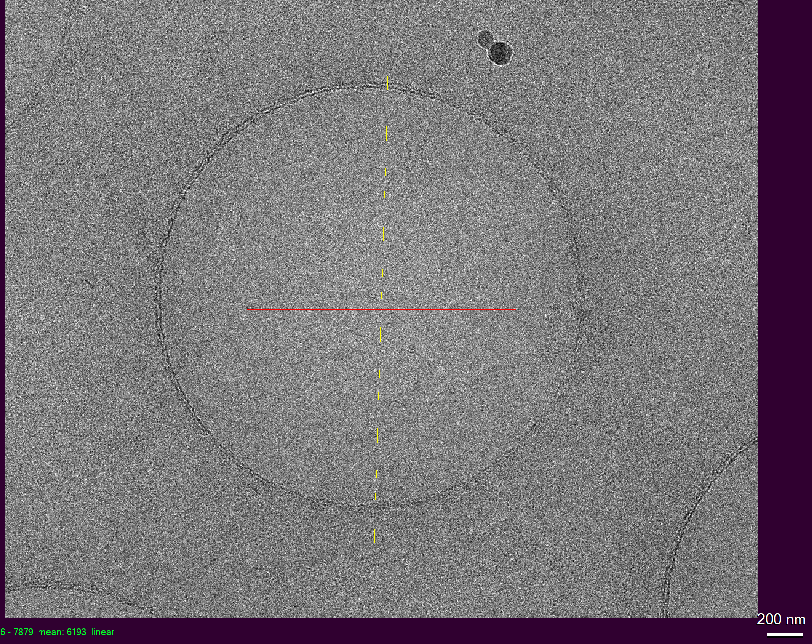
- Now you will see an image with the hole in the center (Figure 23). Hint: This is a good moment where you could check again the position of your focus and trial mode beams.
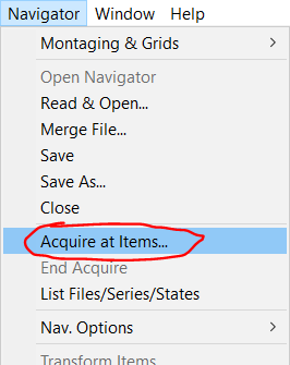
- Go to "Navigator --> Acquire At Items" (Figure 24)
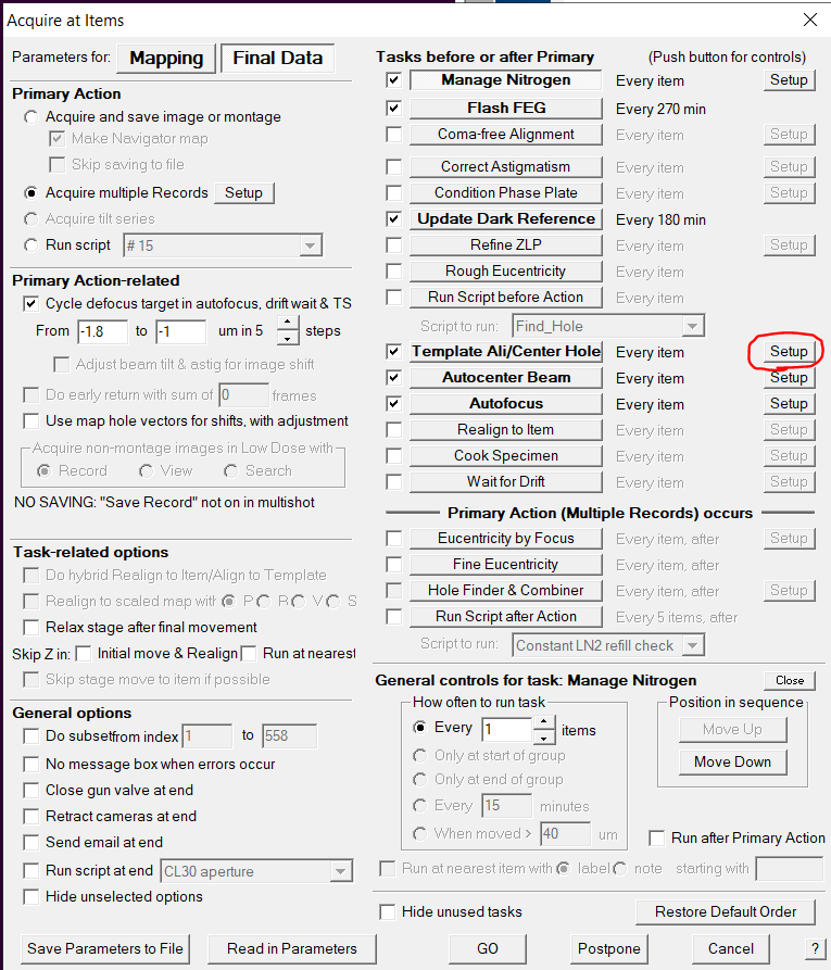
- Under the "Final Data" tab on the right side under hole targeting click on "Setup" (Figure 25)
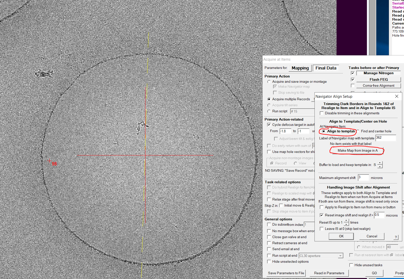
- In the new window make sure that "Align to template" is selected and then click on "Make map from image in A" (Figure 26). Note: A few steps below you find the alternative if you want to use FindAndCenterHole
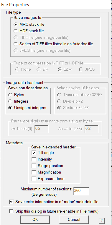
- In the just opened file properties windows click "OK" (Figure 27).
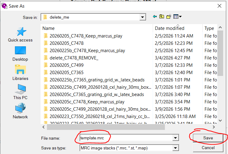
- In the next dialogue make sure that you are in the correct folder location of your current grid and give a file name for the template, i.e. template.mrc. Click "Save" (Figure 28).
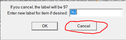
- Click "Cancel" So that SerialEM uses automatically the next logical label number (Here: 97) (Figure 29)
- The label for the Navigator map with template is changed automatically to the new number (Here 97). Click "Ok" to confirm the hole targeting setup (Figure 30).
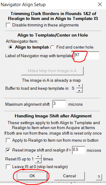
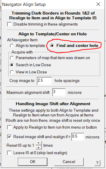
- Variation: If you prefer to use the Find and Center Hole routine instead of reference target select the "Find and center hole" option in the Navigator Align setup window (Figure 31).
Final Shift to marker
- Before starting the actual data collection we need to make sure to use the fully correct stage coordinate so that we target the proper holes.
- Open one of the square maps by left clicking on the item in the navigator window (Figure 32)
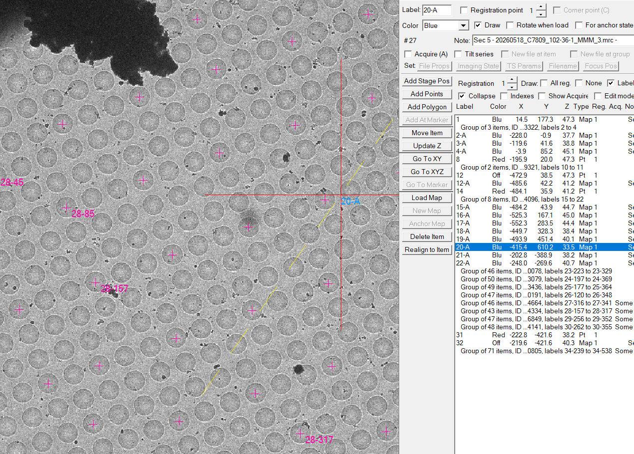
- If this square contains a suitable feature click in the Navigator Window on "Add points" (Figure 33).
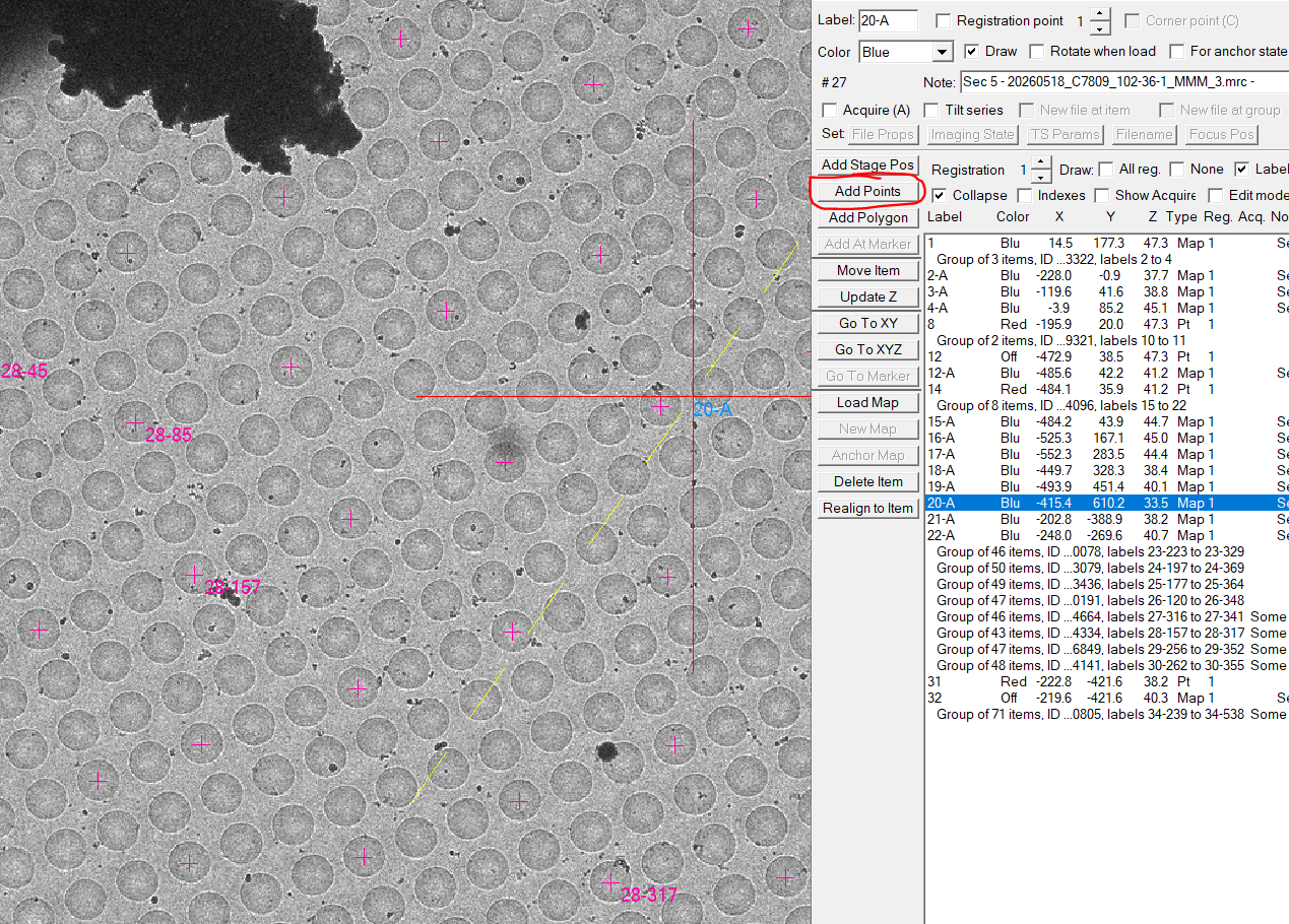
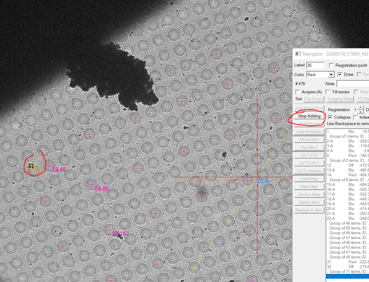
- Left click on the feature in the square image and click "Stop Adding" in the navigator window (Figure 34).
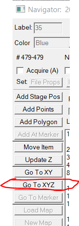
- With the feature point highlighted in the navigator window click "Go To XYZ" to move the stage to the feature (Figure 35).
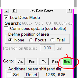
- Go to Search mode beam condition by clicking "Sea" in the pink panel (Figure 36).
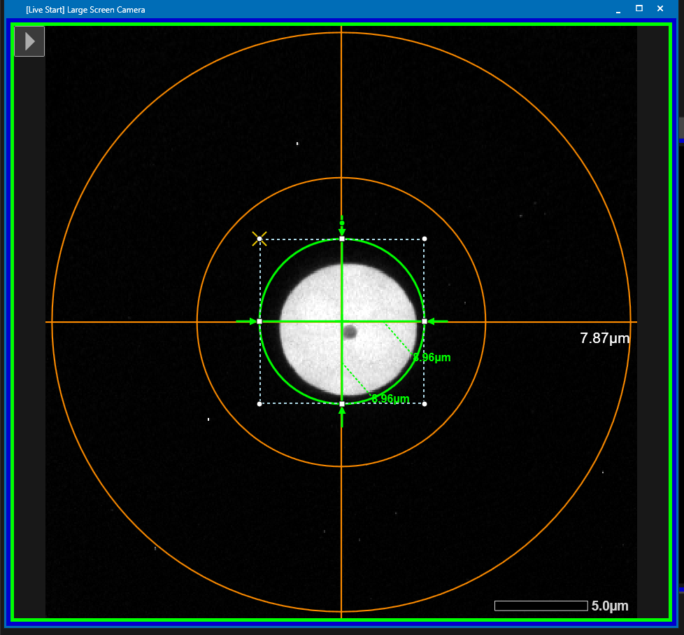
- Put down the large phosphor screen (Right hand panel, Screen retract).
- On the phospohor screen you may already see the feature and can center the feature in the middle of the screen using the trackball (Figure 37). Note: If you do not see it immediately either look in the near neighborhood or remove temporarily the CL aperture. Don't forget to put it back in
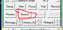
- Make a picture in Search mode by clicking "Search" in the dark green panel (Figure 38).
- The image should contain the feature you tried to center. Make a left click on the feature which will create a green cross (Figure 39).
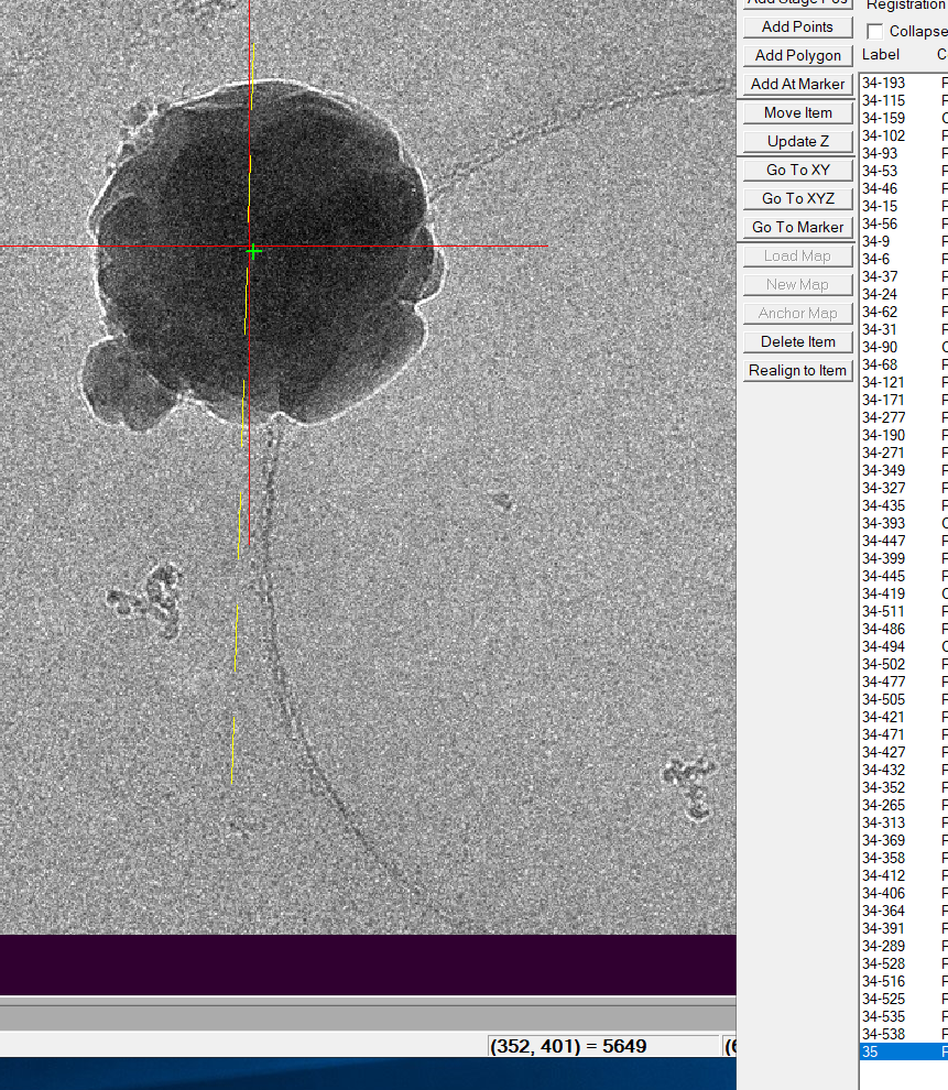
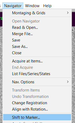
- While the feature item is still highlighted in the navigator window click in the Menu bar on "Navigator --> Shift to Marker" (Figure 40).
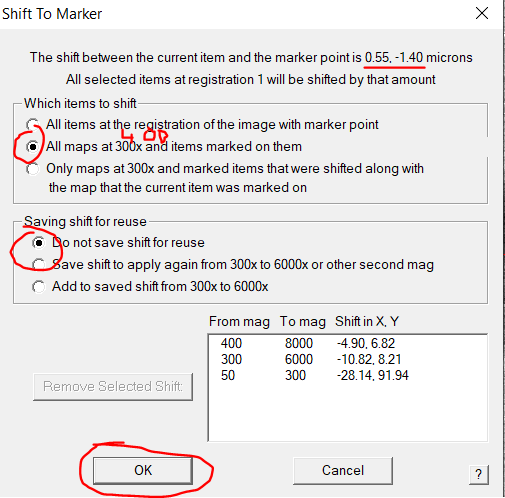
- Check the total shift displayed in the to of the window. In general I expect no more than 4 um offset (Figure 41). If it is more you may have done something wrong.
- In the new window make sure to select " All maps at 400x magnification" and "Do not save shift for reuse" (Figure 41).
- Click "OK".
Startup data collection
- If not done before, check that the background job is running in the terminal window (Figure 42).
- If the job would not be running or the terminal is closed, open a terminal and go to the proper folder using cd (Figure 32) and start the bat script of Yoneo (Figure 43).
- Go back to menu "Navigator --> Acquire at Items" and adjust the target defocus value in the Primary Action related panel (Figure 44).
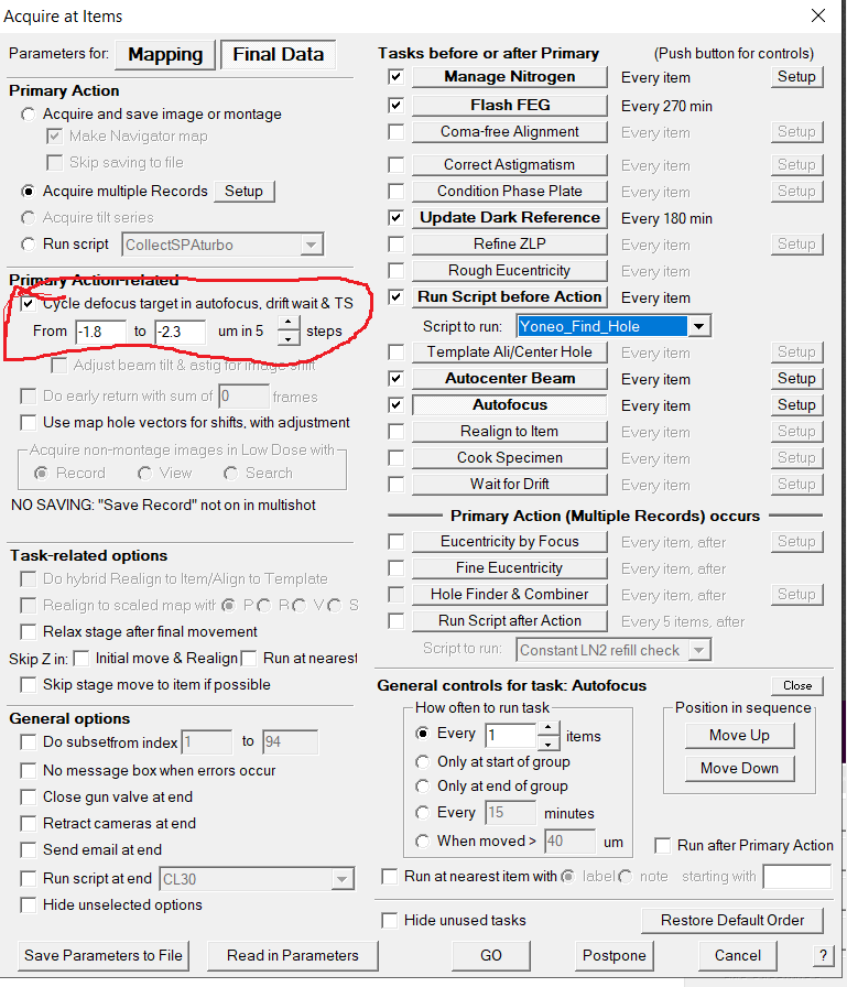
- Under Primary Actions click on "Setup" for "Acquire multiple record" (Figure 45)
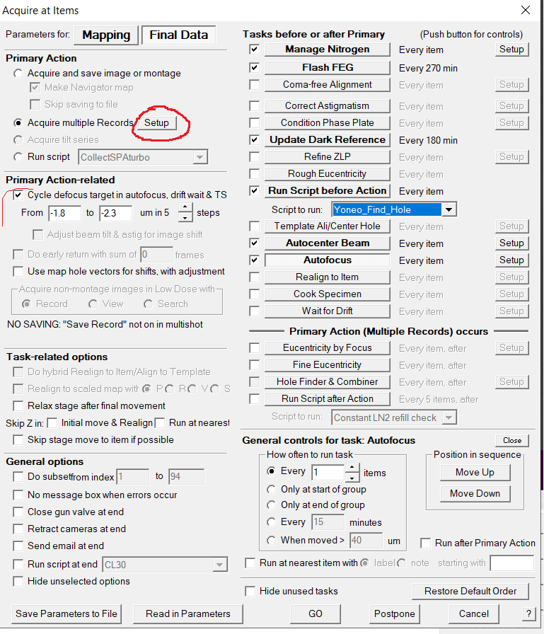
- Ensure that the multiple records parameters are set properly by clicking on the Setup button next to "Acquire multiple records" (Figure 46).
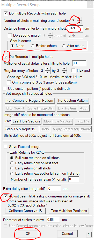
- Make sure that the parameters are correct and you (i) do multiple records within each hole, (ii) have the right number of shots in the hole, (iii) do records in multiple holes and (iv) have the correct regular hole pattern (Figure 44).
- If this is fine click "OK" in the Multiple Record Setup Window (Figure 46).
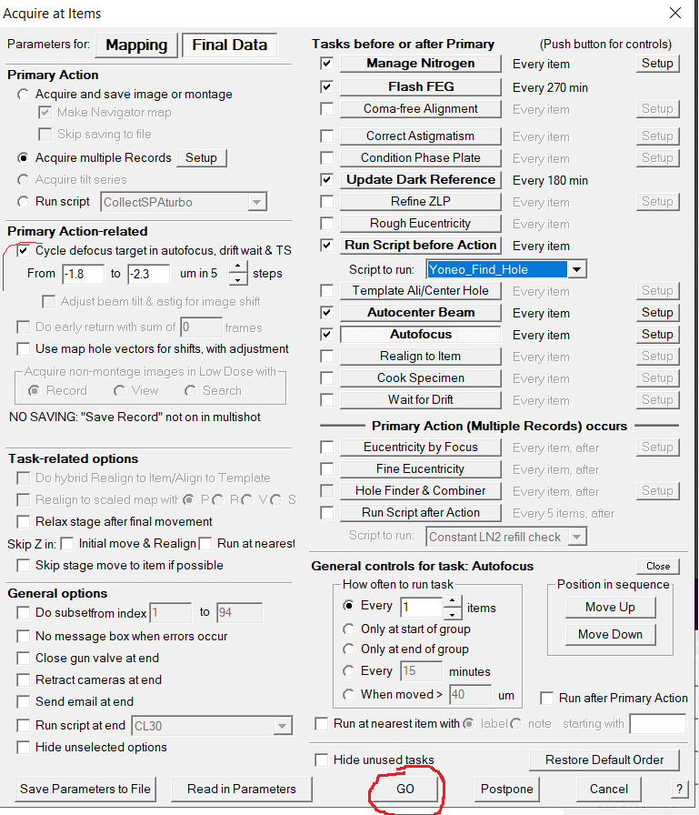
- Click "Go" in the Acquire at Items dialogue (Figure 47)
- Important: NEVER stop the data collection by hitting STOP in the dark green panel. If you did, you need to redo coma free alignment.
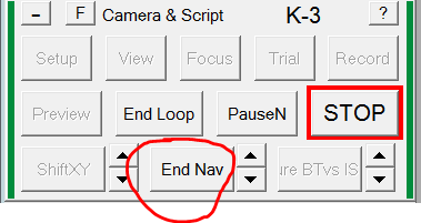
- If you want to change any parameters or re-start with an updated navigator file, hit "End Navigator" (dark green panel) (Figure 48) and wait until the current acquisition target loop is finished. The big red STOP button will be gone when finished.
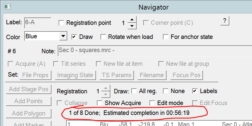
- Note: In the navigator window you can see the number of targets left and the estimated completion time (Figure 49). The values will stabilize after a few rounds.
Unclipping cartridges
Note: Never touch the cartridge with your bare hand. If you touch it use gloves.
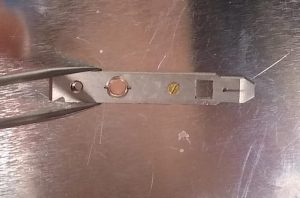
- Hold the cartridge with a blunt tweezer on one side (Figure 1). Alternatively: Use your fingers to hold the cartridge and cover one half of the clipring.
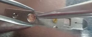
- Use an old tweezer (it will have a bend tip, but needs to be thin) and go, via one of the cartridge side grooves, with the tweezer below the clipring (Figure 2). Note: It helps to use the groove which is the furthest away from the open side of the clip ring.
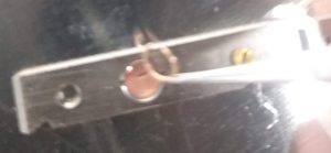
- In a continuous motion slide the tweezer in and grab the clipring, which will jump out fast from the cartridge (Figure 3). Having the finger with gloves half on the clipring can help. Important: These clip rings are expensive and reusable. Do not loose them.
- Use the cartridges for clipping new grids after drying or store them in the small glass vessels.
SerialEM crashes and recovery
SerialEM stall (mainly during square montage)
Problem: During square montaging you may see that it is not progressing. Indicators are
- Estimated time of completion increases
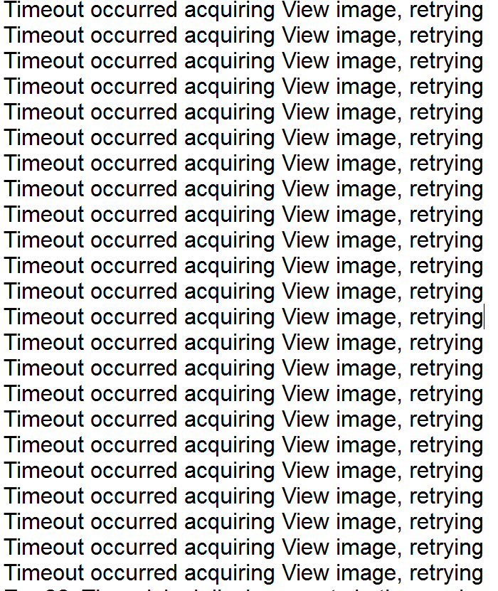
- log file prints out excessive repeat warnings of "Timeout occurred acquiring View image, retrying" (Figure 1)
Solution:
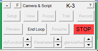
In SerialEM green panel click 'Stop" (Figure 2). Note: This is the one time it is OK to actually hit stop. In general don't do this.
Afterwards you can simply continue the square montage via Navigator--> Acquire At Items". All previously collected squares are still available.
SerialEM crashes (mainly during square montage or grid atlas collection)
Problem: SerialEM has a fatal crash and the error message may show as below (Figure 3) or even without any error message
Solution:
Acknowledge the error by clicking "OK" or SerialEM may have close completely by itself.
Restart you SerialEM executable of choice from the Desktop
Go in Low Dose Mode (Pink panel) and Go to Record Mode (pink panel)
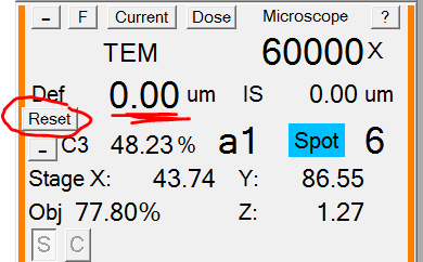
Hit "Std Focus" (right hand panel, Important: it's a double click). The displayed defocus in SerialEM (orange panel) may not show 0 um (Figure 4)
In SerialEM click "Reset" in the orange panel. The displayed defocus should be 0 um (Figure 4).
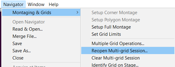
To reopen your previous multigrid session go to Navigator --> Montaging and Grids --> Reopen Multigrid session (Figure 5)
Go to your folder and find the adoc file with your current date. Click "OK" to open (Figure 6)
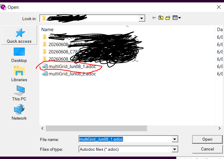
Problem:
TEM center crashes and recovery
Problem: TEM center crashed with most likely an error of an unhandled exception (Figure 1).
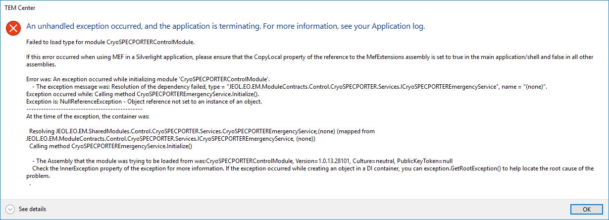
Solution:
Confirm the error message (Note: If SerialEM is still running, there is no need to close SerialEM)
Make sure that all three subprograms are close. Otherwise close them in the taskbar on the bottom right (Figure 2). These are "TEM Detector Service" (camera icon), "CSP controller" (blue icon) & "TEM external Server" (here: green square, but may be red or yellow).

Finally restart TEM center suite launcher (Figure 3). Important: NOT the TEM center icon
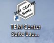
Once the TEM center is open an "Open project" window appears (Figure 4). Click on "cancel".
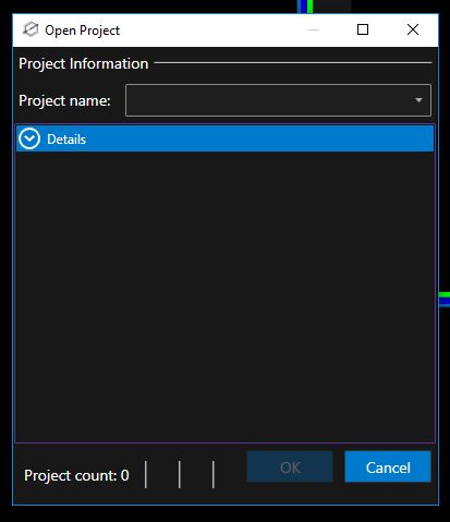
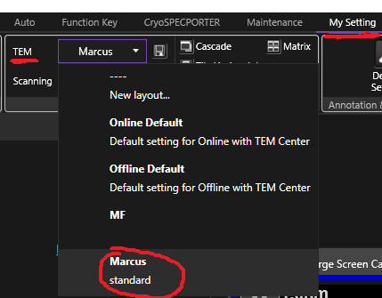
To recover the familiar window setup select in TEM center menu "My setting --> TEM --> Marcus (standard)" (Figure 5).
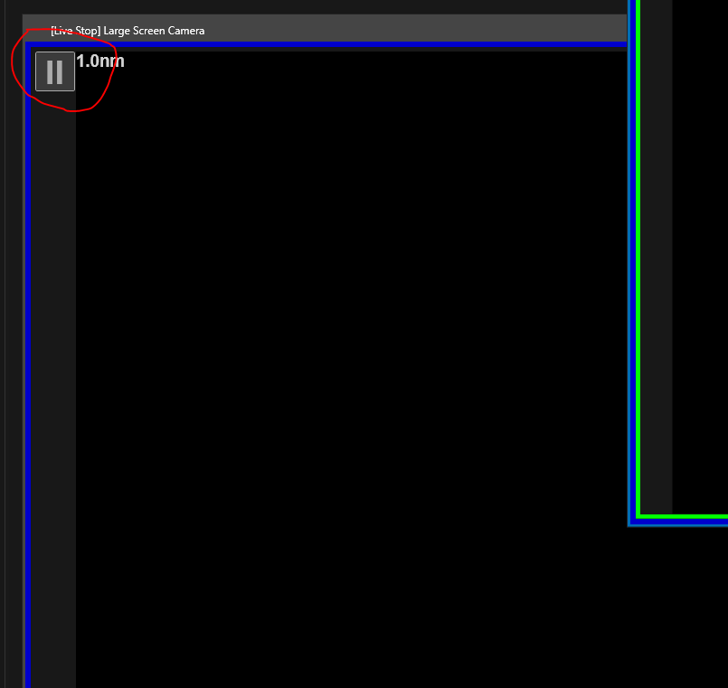
To be able to see things on the phosphor screen click on the pause icon (Figure 6), which will start the camera view and change the icon to a play button. This is possible for both the large and the small screen.
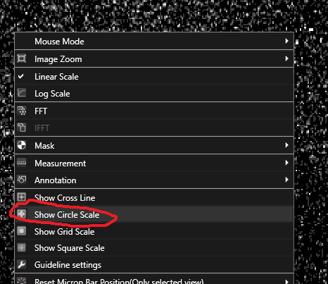
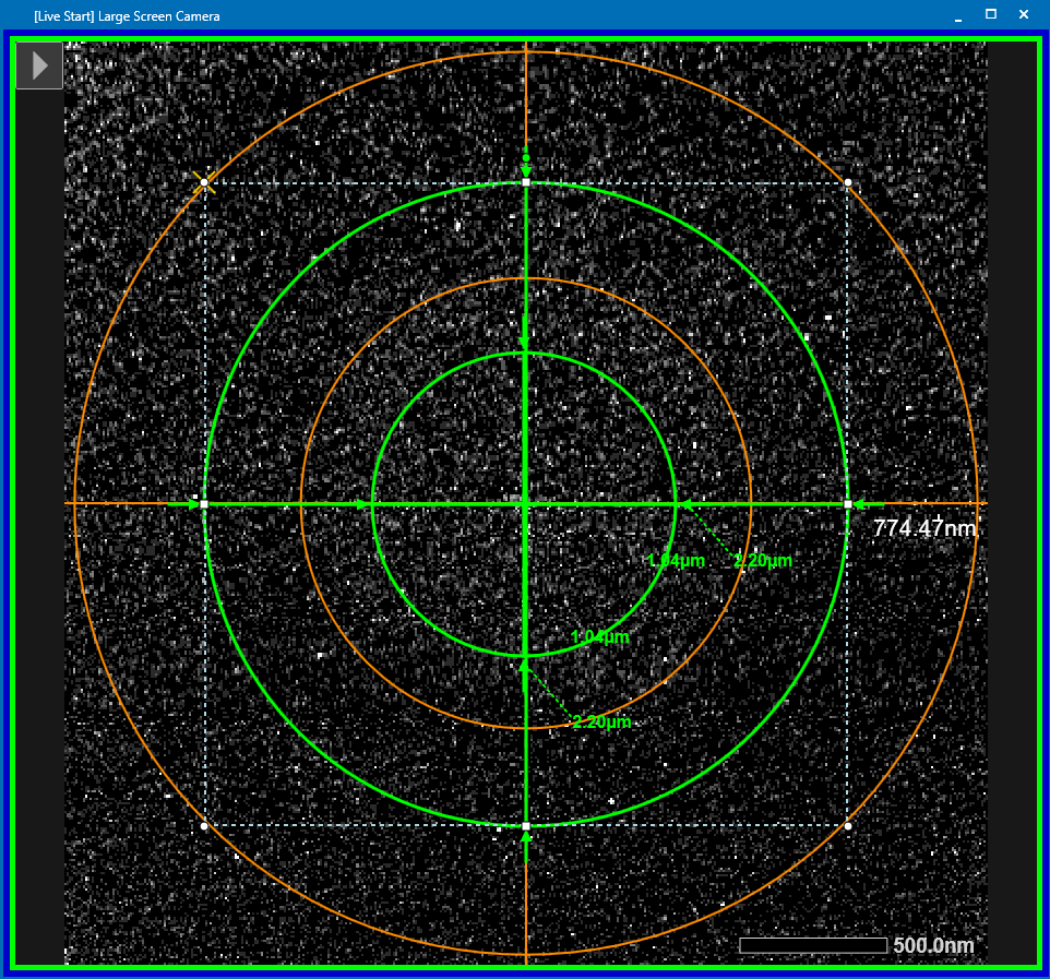
Redraw the circle scale by right clicking on the phosphor screen and select "Show circle scale" (Figure 7).
To redraw the green indicator circles on the phosphor screen, right click on the screen and left click "Measurement --> Ellipse" (Figure 8).
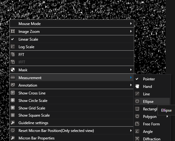
Then while pressing Shift, keep left mouse button pushed and drag until you reached the desired circle size. I recommend two circles, 1.04 um and 2.2 um. Note: These numbers only fit if you are at 60k magnification.
Note you can afterwards still change the size of the circles and drag them to the center for a final result as in Figure 9.
Gatan Camera crashes and recovery
Sometimes Gatan can crash. This may be either just a software crash (currently most likely) or an actual hardware crash. Both are easy to solve. You can add your email to a script to be informed by email about DM crashes automatically.
Software crash
If DM (Digital Micrograph) crashed, it's icon is missing from the bottom bar and SerialEM will have stalled with an error message
- Do not yet touch SerialEM.
- Re-open DM by clicking on it's software icon on the Desktop (Figure 1).
- Be patient, as it takes a few moments.
- Once the program is up and controllable open the panel of "Camera monitor" on the left hand side (Figure 2).
- Wait until the light of the "Health Status" turns green (Figure 2). Note: If it will never turn green and goes red, you have a hardware crash/problem of the camera.

- Once the light is green you can go back to SerialEM and confirm the error message with "OK". SerialEM will remain in a Paused state.
- If the beam valve closed in the meanwhile, re-open the beam valve (left hand panel).
- In SerialEM just click on "Resume N" (Resume Navigator) and the collection will just continue (Figure 3). Note: It will take some time for the camera to be inserted, don't panic!
Automatic Emailing for DM software crashes
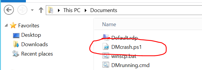
- On the Camera PC go to the "Documents folder" (Figure 1).
- Open the file DMcrash.ps1 with a text editor (right mouse button) (Figure 1).
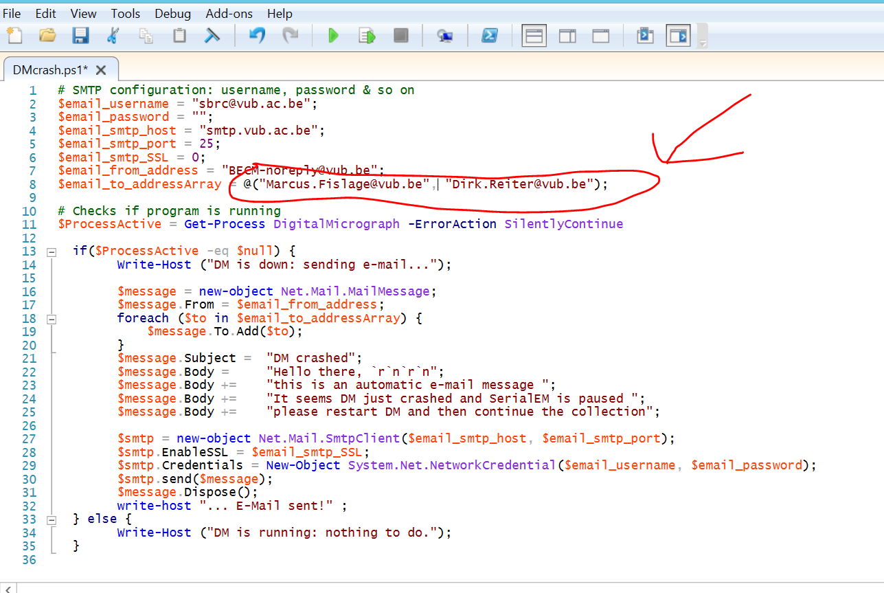
- In line 8 add your email address (comma separated and in quote marks) (Figure 2).
- Save the file (File-->Save) and close the window.
Hardware Restart Gatan K3
- Before you assume that it is a hardware problem, ensure that it may not be just a software issue.
- Therefore, test a restart of the Gatan DM software as described above first.
- If the software restart did not work, close DM3 and close SerialEM (Save navigator, settings and log first).
- Wait 1 minute for the Camera to retract fully.
- Shut down the camera PC.
- Go into the technical room and shut down the Camera Power supply, by touching the large G-icon (Power supply is located on the top of the left rack).
- Wait 1 minute.
- Restart the Camera power supply (Power supply is located on the top of the left rack).
- Wait 5 minutes.
- Restart the Camera Computer (The computer is located on the top of the rack on the back left)
- Log in to the System (password is written on the physical PC in the technical room)
- Open DM by clicking on the Deskop icon (Figure 1).
- Be patient, as it takes a few moments.
- Once the program is up and controllable open the panel of "Camera monitor" on the left hand side (Figure 2).
- Wait until the camera cooled stably back to -20 degrees and the light of the "Health Status" turns green (Figure 2). Note: If it will never turn green and goes red, you have to repeat above procedure.
- Make one test image to ensure the camera is reacting properly (either using SerialEM or DM itself). Note: It will take some time for the camera to be inserted, don't panic!
- You will need to make a fresh gain reference to be sure
Camera temperature not stable warning in SerialEM
- This is more a bug than a problem and mostly/only happens if you are running a script after a restart of the DM software and/or hardware.
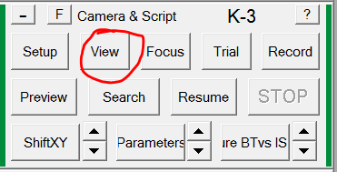
- Just make a single view image with SerialEM (dark green panel, View) (Figure 1).
- Normally it will just have made the image and you can continue your previous operation.
- If it did not work, wait a few seconds and make again a new view image (Figure 1).
Calculate coma vs IS matrix
It is recommended to do this matrix calculation before deciding to adjust the pivot points. The pivot points are mostly stable and don't need adjustment.
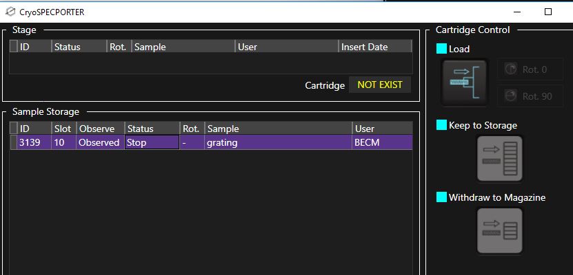
- If not yet done, insert alignment grid by highlighting the grating grid (with latex beads) in the CryoSpecporter and click on load. (Figure 1) Note: If there is another grid still on the stage it will be automatically unloaded.
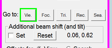
- Ensure that there are at least 6 um of grid around your current location, by first selecting View mode in Serial EM ("Vie., pink panel) (Figure 2).
- Put down the large Phosphor screen ("screen insert", right hand panel).
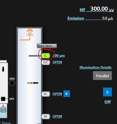
- Remove the CL aperture (double click on CL in microscope pictogram, TEM center) (Figure 3).
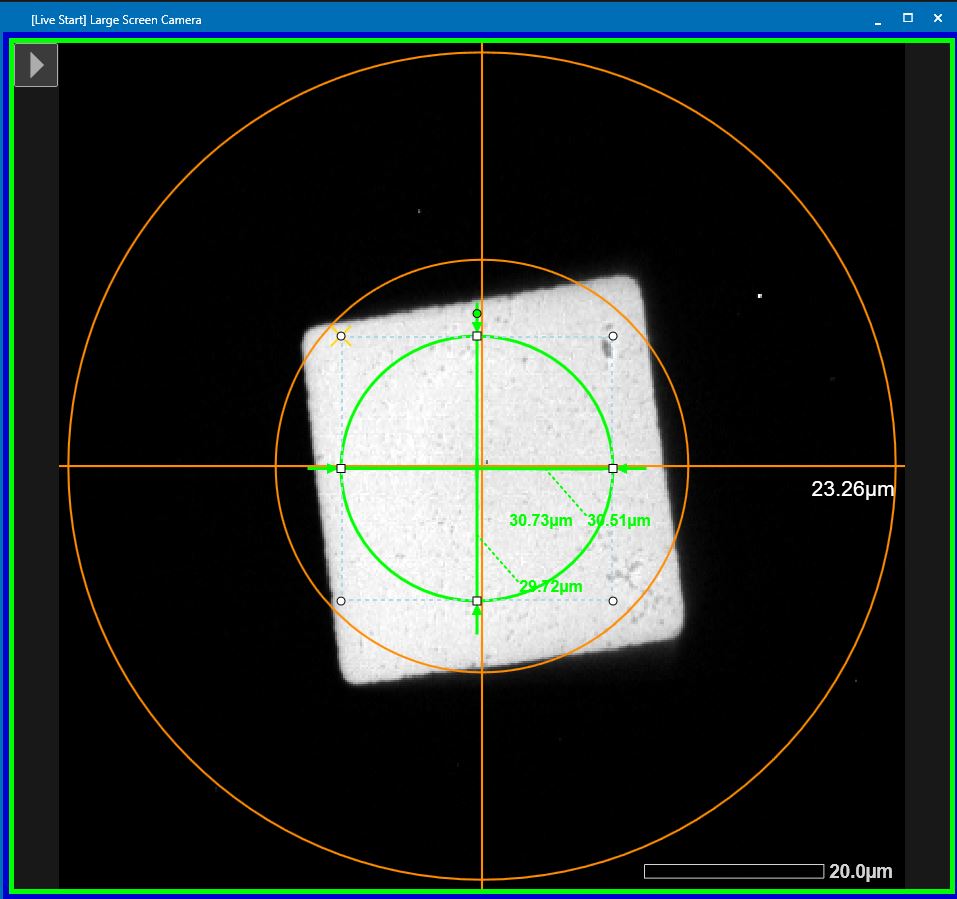
- Move the stage with the tracking ball to a suitable location (Figure 4).
- Re-insert the CL aperture (double click on CL in microscope pictogram, TEM center) (Figure 3).
- Select record beam conditions in SerialEM (pink panel, Rec.) (Figure 5).
- Go to standard focus by double clicking “STD Focus” (right hand panel).
- Ensure that you are at eucentric height. Note: Use rough eucentric for a rough targeting. Measure the actual defocus in SerialEM (Menu –> Focus/Tune –> Measure defocus). The log file will display the actual defocus. Use the Z up and Z down buttons (small panel) to adjust the eucentric height and confirm/readjust with “Measure Defocus”. Note: If you measure too fast after stage x,y or z-motion there is still residual drift and this will lead to a mis-estimation of the actual defocus
- Put down the large phosphor screen by clicking "Screen retract" (right hand panel).
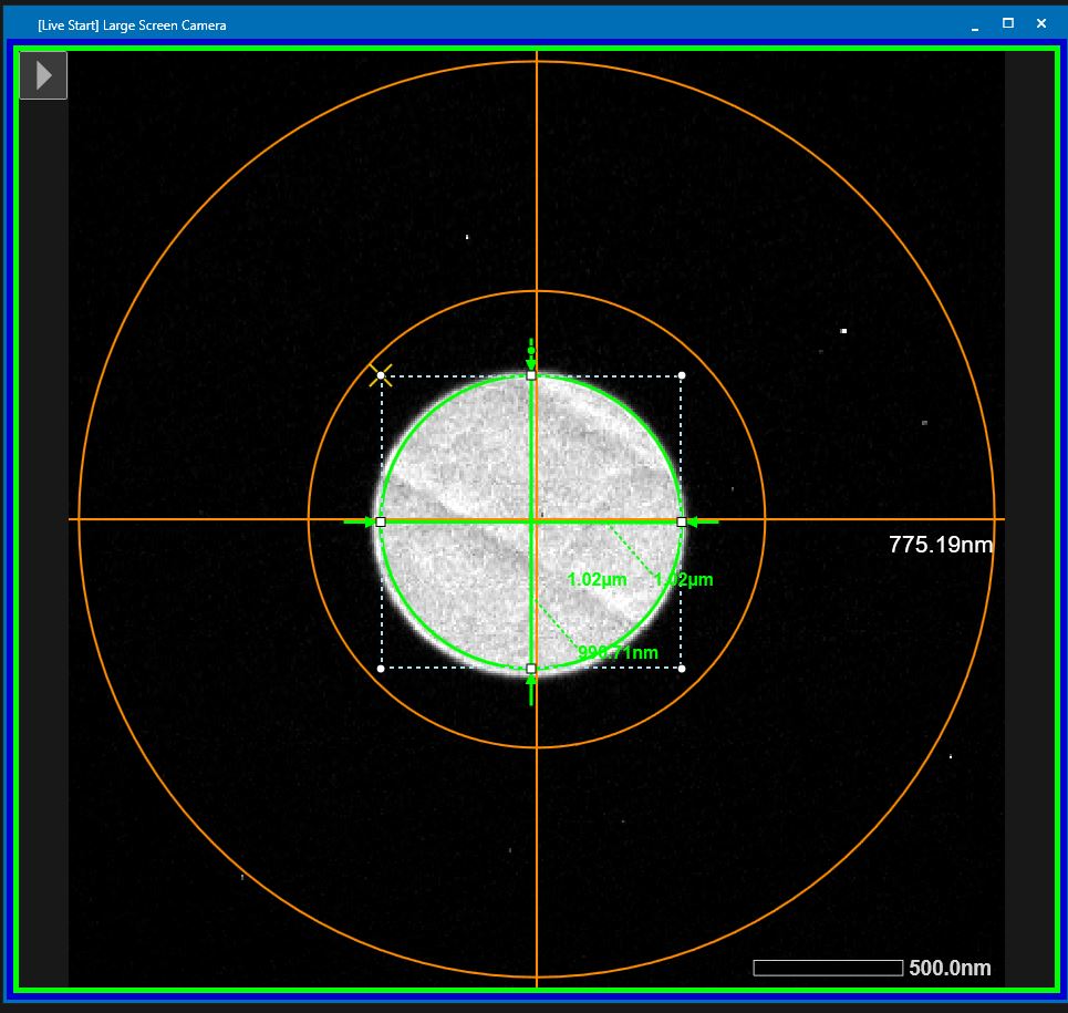
- Center the beam with “Shift X&Y” button on the large phosphor screen (both hand panels) (Figure 6).
- Ensure that there is no residual drift at this moment. Wait until good.
- Define a target defocus by clicking in the SerialEM Menu bar on Focus/Tune --> Set Target (Figure 7).
- Set the target to -1.3 um defocus (Figure 8).
- In the Menu bar go to Focus/Tune --> Autofocus to do auto-focusing (Figure 9). Hint: If the focus position ends up in the hole and focusing fails, you may want to temporarily set "Define position of area -- Focus" to 0 um offset. Undo this before starting the data collection.
- Do coma free alignment by clicking in the Menu bar on "Focus/Tune --> Coma-free alignment by CTF" (Figure 10). Important: Check in the FFT image that the fit (yellow dashed lines) corresponds to measured location of Thon rings.
- The log file reports the amount of beam tilt correction (Figure 11). Hint: High score and low fit to values indicate a good run.
- Do astigmatism correction by clicking in the Menu bar on "Focus/Tune --> Coma astigmatism by CTF" (Figure 12).
- The log file reports the amount of OL stigmator correction (Figure 13). Hint: High score and low fit to values indicate a good run.
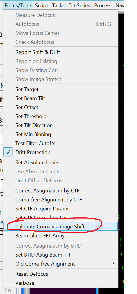
- Run the Coma vs IS calibration by clicking in the Menu Bar "Focus/Tune --> Calibrate Coma vs Image Shift". Important: For each tilt direction control the amount of beam tilt needed. It should be relatively symmetrical and less than 2 mrad. If not: check pivot points. If pivot point are for sure still good, check gun alignment (Gun alignment should be done by staff only!!!).
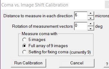
- Confirm the parameters and click "Run calibration" (Figure 15)
- At the end of the procedure the log file displays values for BT vs IS and STIG vs IS (Figure 15).

- Save the calibration by clicking in the Menu Bar "Settings --> Save" (Figure 17).
Pivot point alignment
These pivot points are rather stable and it is recommended to change them only if you get unusually large beam tilt values in the coma vs IS matrix.
Insert grating grid
- Insert alignment grid by highlighting the grating grid (with latex beads) in the CryoSpecporter and click on load. (Figure 1) Note: If there is another grid still on the stage it will be automatically unloaded.
- Once insertion is finished you can open the beam valve. Note: If the beam valve icon is still gray shaded in the pictogram, you still need to wait a few seconds.
Beam tilt pivot points
- Go to standard focus by double clicking “STD Focus” (right hand panel).
- Ensure that you are at eucentric height. Note: Use rough eucentric for a rough targeting. Measure the actual defocus in SerialEM (Menu –> Focus/Tune –> Measure defocus). The log file will display the actual defocus. Use the Z up and Z down buttons (small panel) to adjust the eucentric height and confirm/readjust with “Measure Defocus”. Note: If you measure too fast after stage x,y or z-motion there is still residual drift and this will lead to a mis-estimation of the actual defocus
- Select record beam conditions in SerialEM (pink panel, Rec.).
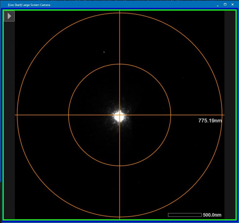
- Condense the beam to a small point (Brightness dial, left hand panel) and roughly center the beam on the large phosphor screen with “Shift X and Y”(both hand panels) (Figure 2).
- Insert small phosphor screen “FS retract” right hand panel.
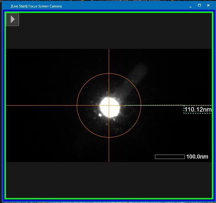
- Condense the beam further into a very small dot (Brightness dial, left hand panel) and center the beam on this Focus screen with “Shift X and Y” (both hand panels) (Figure 3).
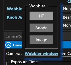
- Open the wobbler window in TEM center through the “Lens/Deflector” window by hovering over “Wobbler” and clicking on “Wobbler window” (Figure 4).
- Select in the new window “Tilt X” (Figure 5). CL Comp tilt will be automatically assigned to the Def/Stig knobs.
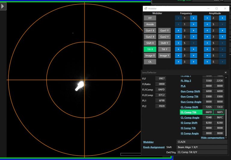
- Use “Def/Stig X” knob (left hand panel) and minimize the displacement of the major beam along the wobbling axis. Note: You can use Beam shift if you will lose the beam from the small Phosphor Screen.
- If there is perpendicular motion to the wobbling axis, CL comp angle needs adjustment. Otherwise continue with point 16.
- Assign CL Comp Angle to the "Def/Stig: knobs via Lens/Deflector window –> CL Comp Angle –> Assign to knobs”.
- Click on one of the “Def/Stig” button to go into coarse mode.
- Use the “Def/Stig X”button to minimize the lateral motion against wobbling axis.
- Click on one of the “Def/Stig” button to go back into fine mode.
- Assign CL Comp Tilt back to the "Def/Stig: knobs via Lens/Deflector window –> CL Comp Tilt –> Assign to knobs”.
- Switch off “Tilt X” and switch on “Tilt Y”.
- Use “Def/Stig Y” knob (left hand panel) and minimize the displacement of the major beam along the wobbling axis. Note: You can use Beam shift if you will lose the beam from the small Phosphor Screen.
- If there is perpendicular motion to the wobbling axis, CL comp angle needs adjustment. Otherwise continue with point 24.
- Assign CL Comp Angle to the "Def/Stig: knobs via Lens/Deflector window –> CL Comp Angle –> Assign to knobs”.
- Click on one of the “Def/Stig” button to go into coarse mode.
- Use the “Def/Stig X”button to minimize the lateral motion against wobbling axis.
- Click on one of the “Def/Stig” button to go back into fine mode.
- Assign CL Comp Tilt back to the "Def/Stig: knobs via Lens/Deflector window –> CL Comp Tilt –> Assign to knobs”.
- Switch off “Tilt Y”.
Beam tilt
As above you still need to be at standard focus and eucentric height.
Ensure that there is not residual drift from sample insertion or liquid nitrogen refilling.
- Remove the Small Focus Screen (“FS insert”, right hand panel)
- Put the beam in parallel mode by loading record mode from SerialEM (“Rec.”, pink panel)
- Center the image with the phosphor screen using the stage on one of the latex beads, center the beam (Figure 6).

- Insert the small focus screen “FScreen retract”, (right hand panel).
- Center the latex bead on the screen using the trackball.
- Paint a circle around the position of the latex bead (TEM Center menu –> Tools –> Ellipse)
- Change the defocus to between -10 to -15 um (“Image/diff focus button”, right hand panel). If there is significant beam tilt you will see that the image starts moving.
- Switch on “Bright tilt” (Left hand panel). This will assign BeamAlign2 to the Def/Stig knobs.
- Center the latex bead again on its original position using “Def/Stig X&Y” buttons (both hand panels, use coarse mode).
- Hit standard focus (Std focus, right hand panel).
- Repeat steps 31-34 until the bead does not change its position during defocusing.
- Switch off “Bright tilt” (Left hand panel).
Beam shift pivot points
From before you should still be at standard focus and eucentric height. You should also still have a latex bead in the center of the focus screen
- Remove condenser lens aperture (CL button, microscope pictogram, TEM center).
- Set defocus to -40 um (“Image/Diff focus” button, right hand panel).
- In the Lens/Deflector window hover over “CL Comp Shift” and push “assign to knobs”.
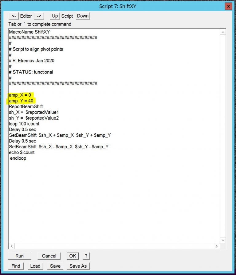
- In SerialEM edit the script Shift X,Y (menu –> Script –> Edit –> Edit 6 (or similar)) and put amp_X to 40 and amp_Y to 0, then run script Shift X,Y (Figure 7). You may also want to change "loop NUMBER icount" to between 10-20 dpending how fast you can adjust the pivot point.
- Minimize the movement of the latex bead along the beam motion on the focusing screen using “Def/Stig X”button. Note: There may be image motion perpendicular to the beam motion. Do not try to correct for this!
- Wait until the script stops automatically (length depends on icount number)
- If you stopped the script accidentally, roughly center the beam via Set BEAM ALIGN 1 to default by hovering in the Lens/Deflector window over Beam Align 1 and hit “Default”.
- Edit script Shift X,Y and put amp_X to 0 and amp_Y to 40, then run script Shift X,Y (Figure 7).
- Minimize the movement of the latex bead along the beam motion on the focusing screen using “Def/Stig Y”button. Note: There may be image motion perpendicular to the beam motion. Do not try to correct for this!
- Wait until the script stops automatically (length depends on icount number)
- If you stopped the script accidentally, roughly center the beam via Set BEAM ALIGN 1 to default by hovering in the Lens/Deflector window over Beam Align 1 and hit “Default”.
- Un-assign “CL Comp Shift” from the knobs (via Lens/Deflector window –> CL Comp Shift –> Assign to knobs”). Button will not be green anymore.
- Insert condenser lens aperture (CL button, microscope pictogram, TEM center).
- Push STANDARD FOCUS (“STD focus”, right hand panel).
- Center the beam with “Shift X&Y” button (both hand panels).
Refine Beam shift calibration
This normally only needs to be done if you changed the pivot points.
- Ensure that there are at least 6 um of grid around your current location, by:
- Select View mode in Serial EM ("Vie., pink panel) (Figure 1).
- Put down the large Phosphor screen ("screen insert", right hand panel).
- Remove the CL aperture (double click on CL in microscope pictogram, TEM center) (Figure 2).
- Move the stage with the tracking ball to a suitable location (Figure 3).
- Re-insert the CL aperture (double click on CL in microscope pictogram, TEM center) (Figure 2).
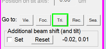
- In SerialEM go to trial mode ("Tri", pink panel) (Figure 4).
- Go to standard focus by double clicking “STD Focus” (right hand panel).
- Put down the large phosphor screen by clicking "Screen retract" (right hand panel).
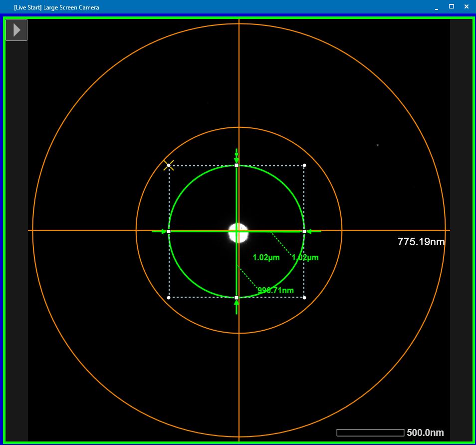
- Center the beam with “Shift X&Y” button on the large phosphor screen (both hand panels) (Figure 5).
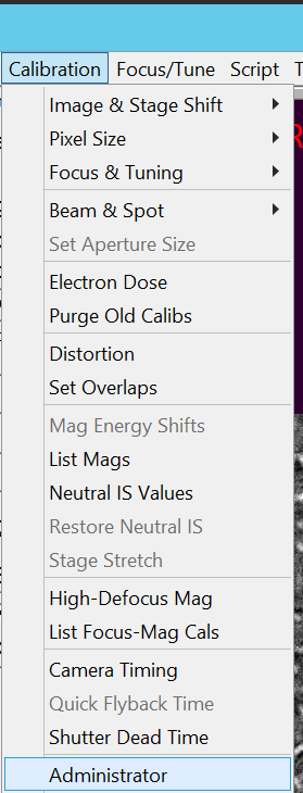
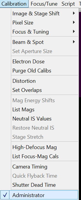
- In SerialEM select in the Menu bar Calibration --> Administrator (Figure 6).
- In SerialEM select in the Menu bar Calibration --> Beam & Spot --> Refine Beam shift (Figure 7).

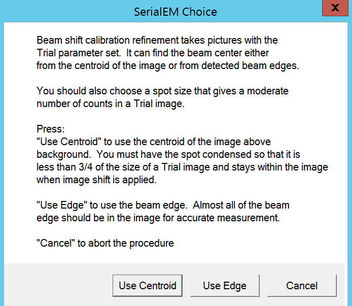
- Confirm window with "Use Centroid" (Figure 8).
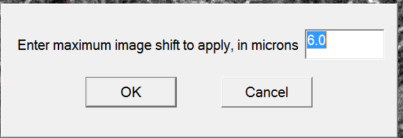
- In the new window, ensure that the selection screen asks for 6 um image shift. Confirm with "OK" (Figure 9).
- The program will first apply a small beam shift in 4 directions and calculate a matrix from the observed beam shift. It will the do the same in 2 rounds with the large image shift. Note: Make sure that the images in all four directions are bright and you are not blocked in calibration by a grid bar.
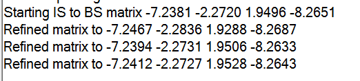
- The log file will print out the refined matrix numbers. Note: If this changed dramatically from the staring matrix you probably have done something wrong while setting the pivot points (Figure 10).
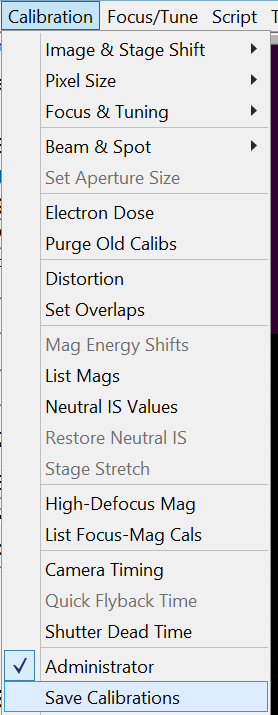
- Save the calibration in SerialEM by clicking in the Menu bar Calibration --> Save Calibrations (Figure 11).
- Get out of Administrator mode by unselecting in the Menu bar Calibration --> Administrator (Figure 12).
Change Liquid nitrogen tank
The full tank last around 8 days, as long as the stage and sample storage tank are filled always simultaneaously.
This happens automatically during the data collection. But if the scope is idle you can use the script "Constant LN2 refill check" in SerialEM scripts panel.
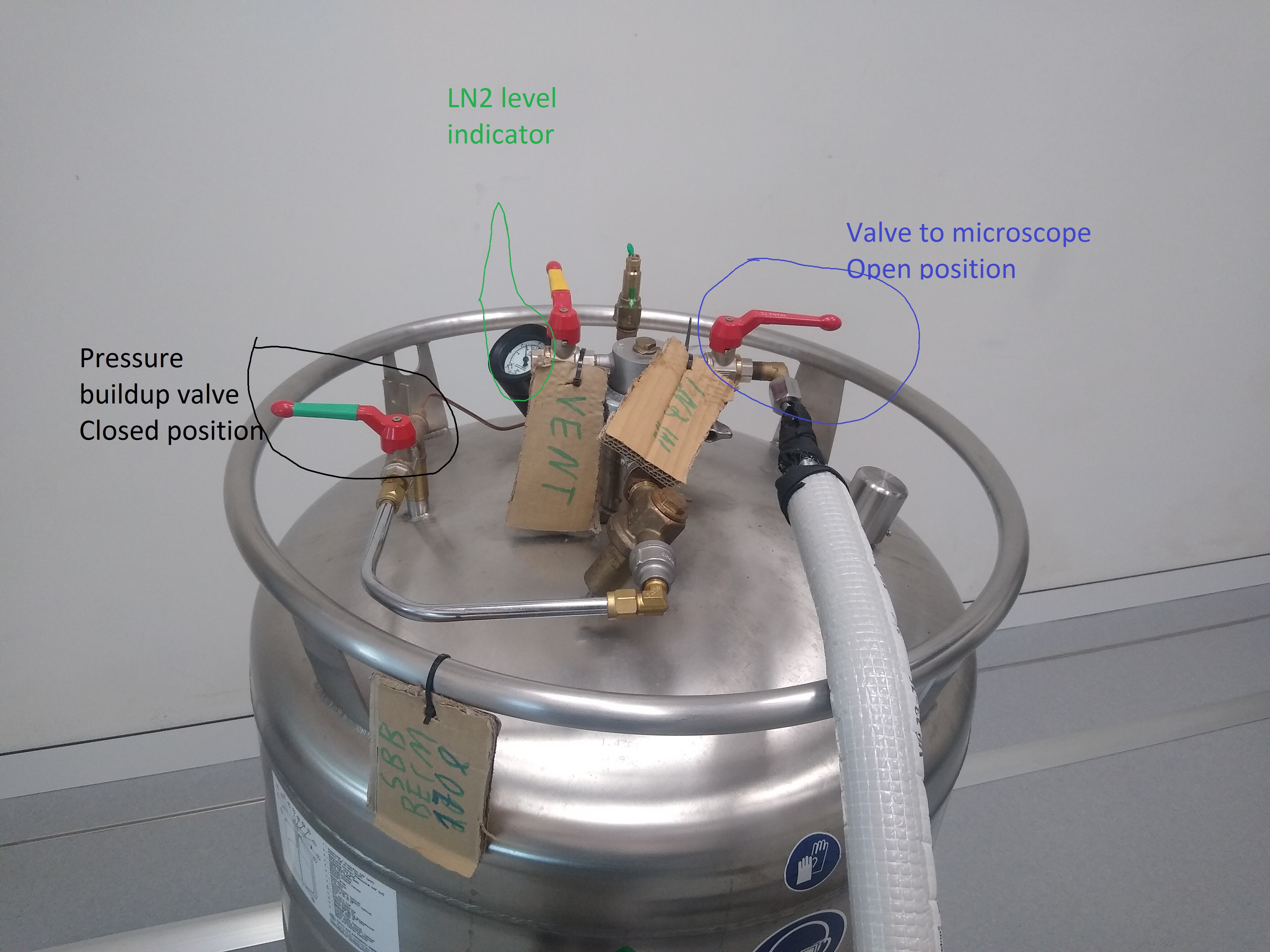
The tank has a level indicator to show how much LN2 is left.
- Check if the tanks are being refilled at the moment (Icon next to microscope pictogram, TEM center) (Figure 1). Wait if so.
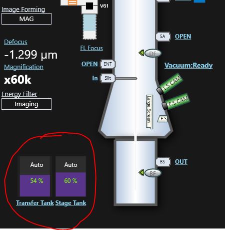
- If the tanks are indicating less than 50 % it is worthwhile to trigger a manual refill. If not, continue step 5.
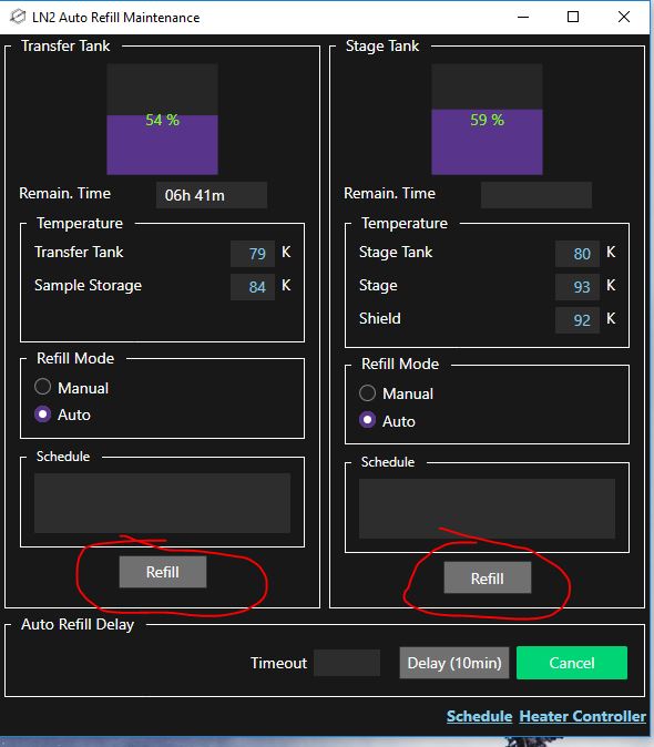
- Open the LN2 Auto Refill Maintenance window (right click on microscope pictogram --> LN2 Auto Refill Maintenance) (Figure 2).

- Click in the LN2 Auto Refill Maintenance widow on "Refill" for both tanks and wait until refilling is finished (Figure 3).
- Enter the microscope room and warm up the hose with the hair dryer, if the connection is icy from a recent refill (Figure 4).
- Close the tank valve leading to the microscope (Figure 4).
- Unscrew the hose leading to the microscope at the tank side (Figure 4).
- Bring the 200 l tank into the technical room to be emptied completely before bringing the tank to the magazine for refill (Figure 4).
- The new full tank should be attached with the hose to the microscope (Figure 4). Make sure the screw is tightened with the wrench. Important: Do not over-tighten!!!
- Open the tank valve leading to the microscope (Figure 4).
- Ensure that the pressure buildup valve is closed (Figure 4).
Perform test shots (alternative)
Under this setup I recommend to make the square pictures of all the squares you would like to test shoot. This goes rather fast.
0. If not done yet, make sure to apply the saved shift from the 50x Mag Atlas to the 300/400x Square Mag for your grid via opening of the navigatoir file (step1) and then "Menu Navigator --> Apply saved shift" (see bottom of make grid atlas section for details)
- Open Navigator by selecting the ID of your grid of interest in the Multi-Grid window and click on "Open Nav" (Figure 1)
- Optional: Insert the grid in which you want to do test shots by clicking on the ID in the multigrid window. (Figure 2) Note: If there is another grid still on the stage it will be automatically unloaded. And it will be automatically loaded if you run the square imaging via multiple grids.
- In the navigator window double click on the item corresponding to your atlas. It is a "Blu" color item (Figure 3).
- In the navigator window click on "Add Points" and make a left click on all squares that you want to try test shots on. The points appear as red crosses in the image and "red" color item in the navigator window (Figure 4).
- Once finished click in the navigator window on "stop adding" (Figure 5).
- In the navigator file put all those point on acquisition by highlighting that group and clicking "A" on the keyboard. Note: If the group of point is displayed separately you can click "collapse group" checkbox
- In the Multiple Grid operations only have the checkbox on the grid active that you want to use (Figure 6)
- Make sure do remove the checkbox from "Acquire Grid Maps"
- Make sure to activate the checkbox from "Acquire Medium Mag Maps"
- Make sure the option LD View is active.
- Click in the Multi Grid Operations Window on "Set Mapping Parameters"
- Make sure that in the newly opened window we have "Rough eucentricity" (Figure 7)
- Click "Postpone".
- Insert CL aperture strip 1 by clicking in the Ten One-line Script window on the "Run" command for SetApertureSize 0 100 (Figure 8)
- Go to View mode by clicking "View" in the pink panel (Figure 9).
- Put down the large phosphor screen by clicking "Screen retract" (right hand panel)
- If necessary, center the beam quickly very roughly using the beam shift X and Y buttons (both hand panels), so that some of the center is illuminated. Note: only some part of the middle needs to be illuminated as this is the location of the camera
- Lift up the large phosphor screen by clicking "Screen retract" (right hand panel)
- In the multi grid operation window click "Start run" (Figure 6)
- A pop up message may appear that is asking you if you inserted the proper aperture. If you did insert the 100 um aperture of CL1 click "Yes" (Figure 10).
- Once all squares are done, each square image in the navigator widow has an entry with a label X-A. You can double click on any of the to open the map (Figure 11).
- With One of the map points highlighted (Figure 11), click under Navigator --> Apply saved shift (Figure 12).
- In the newly opened window the displayed magnification should be 400. Click "OK". Note: If it does not show the right magnification you have the wrong point highlighted in the navigator window (Figure 13).
- In the next window click "Yes" to confirm the offset and apply it to all existing 400x maps (Figure 14). Note: This correction is not perfect, but you should be within 1 hole distance.
- On the first map add a point for some alignment as well as a point in the hole of interest using the "Add points" button in the navigator window (Figure 15).
- Click "Stop adding" in the navigator window (Figure 16).
- Highlight with a left click your first point and click "Go To XYZ" in the navigator window (Figure 17)'
- Go to record beam mode (pink panel, Figure 18).
- Insert the small 30 um CL Aperture by clicking "Run" on the One line Script "SetApertureSize 1 30" (Figure 19)
- Put down the large phosphor screen (Right hand panel).
- Make sure that the CL2 30 um aperture is inserted. If not double click on CL2 on the TEM center microscope icon.
- Remove the energy filter slit ("Slit in" button, right hand panel)
- Center the beam using Shift X and Y dials (both hand panels).
- Re-Insert the energy filter slit ("Slit Out" button, right hand panel).
- Adjust "FL focus" right hand panel dial, so that the beam is visible again. At this point it should always be in the counter-clock turning direction. Important: This always happens if you go back and make square images in LM mode. The lenses will return to normal with more time in Mag mode and you have to later turn the FL focus clockwise to keep it aligned;
- Go to Search beam mode by slicking "Search" in the pink panel (Figure 20)
- If the beam is not centered, activate the "Set" checkbox for Additional beam shift (and tilt) in the pink panel (Figure 21).
- Center the beam using Shift X and Y dials (both hand panels).
- Deactivate the "Set" checkbox for Additional beam shift (and tilt) in the pink panel (Figure 21).
- Lift the large phosphor screen (right hand panel, screen Insert)
- Open the camera parameters window by clicking Setup in the dark green panel (Figure 22)
- In the record panel go to "Set folder" (Figure 23). Ensure that "Save frames" is checked. Note: Feel free here to change exposure time and Frame time, but you mostly don't want to.
- Select correct record folder for your grid on (X:\Serial_EM_raw_data\myGroup\myName\myGrid\) (Figure 24). Click OK.
- In the record panel go to "SetFile options" (Figure 25).
- Change your root file name and click "Ok" (Figure 25).
- Back in the setup window confirm all your changes with "OK" (Figure 23)
- Change the parameters of the single hole record by clicking in the Menu bar on Script --> Edit --> 2:SingleHoleRecord (or similar) (Figure 26).
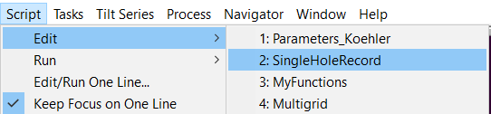
- In the "SingleHoleRecord" script you can adjust the defocus value (DEFOC). the number of shots around the center (NShots), the radius around the center (RAD) and if you want to measure ice thickness (Figure 27). Confirm with "OK". Note: Maximum shot values for 2um holes is 7 shots, 0.69 rad; 1.2 um holes is 4 shots; 0.41 rad; 0.6 um holes 1 shot, 0 rad.
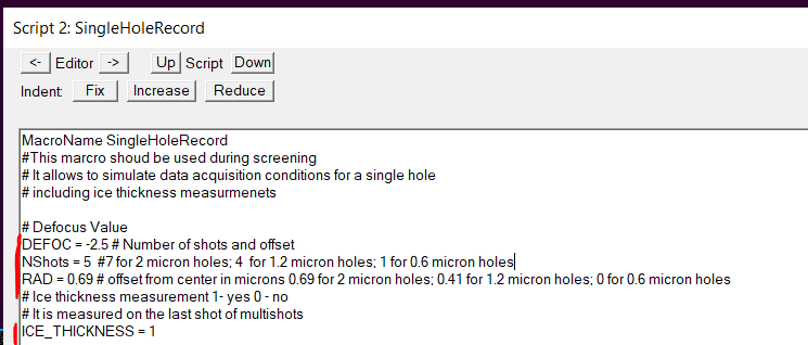
- For safety reason in case of crashes save the setting via the Menu bar Settings --> Save (Figure 28).
- Highlight the hole target item of interest in the navigator window and click "Go to XYZ" (Figure 29).
- Make a Search image by clicking "Search" in the dark green camera panel (Figure 30).
- The camera will make an image at 6k magnification. Change in the ten-One line script window the command "FindAndCenterOneHole" to reflect your hole size. The first number after the letter A is your hole size in micron (Figure 31).
- Click "Run" on that command like to center the hole (Figure 31).
- After the hole is centered make another Search image (Figure 32).
- In the pink panel activate "Focus" under "Define position of area" and make a left click on the image where you want to do the focus on the carbon area (Figure 33).
- In the pink panel activate "Trial" under "Define position of area" and make a left click on the image where you want to do the beam centering on the carbon area (Figure 34).
- In the pink panel activate "None" under "Define position of area" (Figure 35).
- If you do not see the FFT panel it is recommended to open it now via the Menu bar Process --> FFT (Figure 36)
- In the script panel click on "SingleHoleRecord" to do the test shots (Figure 37). Important: If the hole is centered in view mode but the record images hit the carbon area, you need to do a search vs record alignment!
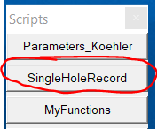
- Repeat Add point, Go to XYZ, search image, FindAndCenterHole and singleHoleRecord (last step) on multiple places on the grid until you know if you have a good grid for data collection or not.
- When finished with test shots, save the navigator file (Navigator --> Save).
- Repeat the whole procedure for all other grids you want to test shoot. Note: Don't forget to change then the folder location and the position of focus and trial mode.