Clipping cartridges for CyoARM300
Clipping cartridges for CyoARM300
If there are no empty cartridges first unclip the used cartridges.
Note: All images are shown without liquid nitrogen in the workstation for easier visibility.

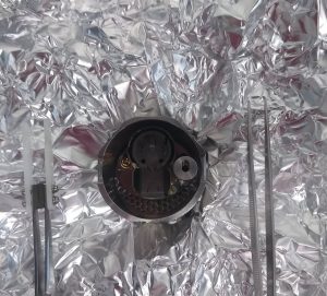
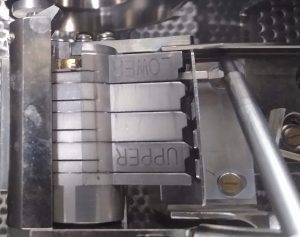
- You can find an empty magazine in the vessel wrapped in aluminium foil in the oven. Never touch it bare handed.
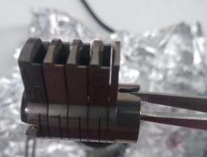
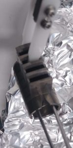
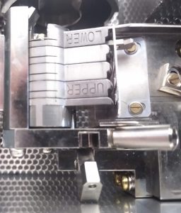
- You can pick up the magazine by putting a tweezer through the two front holes and grab it. (Figure 5 and 6)
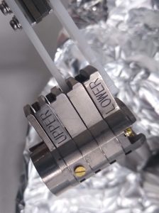
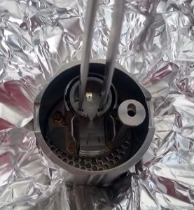
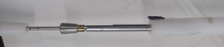
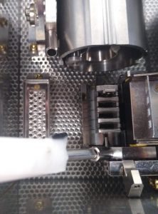
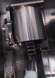
- Now grab the magazine with the white pick up tool as shown in Figure 7 and 8
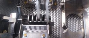
- Put the magazine into the proper position in the workstation. If done well, the magazine is sliding smoothly along the rail (Figures 9 and 10).
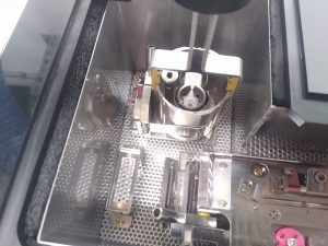
- Grab the cup tightly with the carrying tool and insert it into the workstation. Use the pictogram as a guide to know the proper rotation. It should sit tight.
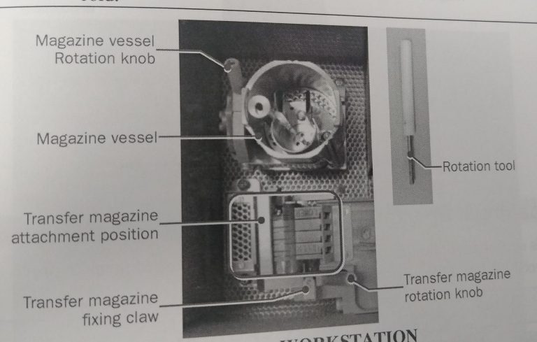
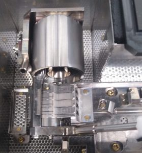
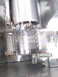
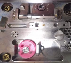
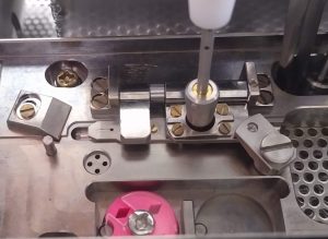
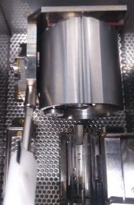
- Cool down the workstation with liquid nitrogen. Once cold, make sure that the liquid nitrogen level is not higher than the specimen attachment area (Figure 1).
- Use the white rotation tool (Figure 1) to turn the cup 90 degrees with the opening towards the magazine (Figure 12).

- Use the white rotation tool to turn the magazine ~90 degrees with the opening towards the assembly site (Figure 13). Once in position (Figure 14), engage the safety pin (Figure 15)
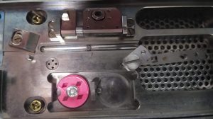
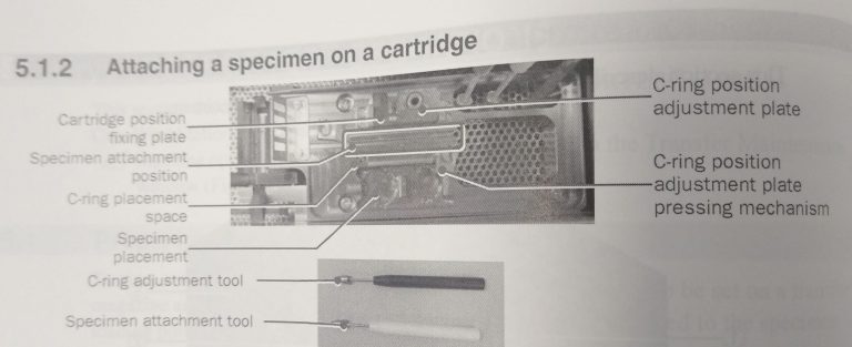
- Place the empty cartridge in the cartridge placement space (Figure 16).
- Place your grid box in the specimen placement area (Figure 16).
- Place the C-ring in the C-ring placement space (Figure 16).
- Ensure that the tip of the specimen attachment tool is properly spread by inserting the rotation tool at the end (Figure 17).
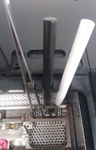
- Put a tweezer, the black C-ring adjustment tool and the white specimen attachment tool into the workstation and make sure they are cooled down before use (Figure 18).
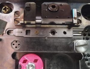
- Put a cartridge with the screw facing you and the square toward the left on the rail of the specimen attachment area (Figure 19). If properly positioned, the cartridge can slide easily sideward.
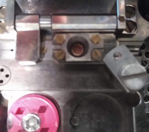
- Align the screw of the cartridge, with the hole of the C-ring adjustment plate and put down the plate. Lock it with the rotation lock (Figure 20). Note: The rotation lock here is not essential but helpful
- Insert one C-ring into the C-ring adjustment plate (Figure 21). Note: The C-ring does not need to be completely flat in position, but not totally tilted either.

- Use the black C-ring adjustment tool to clamp the C-ring in the C-ring adjustment plate by pushing the tool straight down (Figure 22).
- Lift up the C-ring attachment plate and control that the C-ring is properly sitting in the plate (Figure 23). Important: It needs to be straight, otherwise clipping will fail.
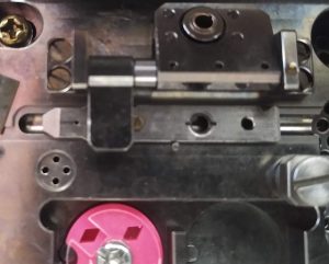
- Move the cartridge further left on the attachment position, so the open square is aligned with the square lock (Figure 24).
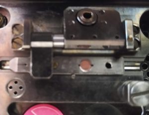
- Lock the cartridge with the square lock (Figure 25). The cartridge should not be able to move sideward anymore.
- Put your cryo grid, top side upwards, onto the cartridge. Make sure its properly positioned in the groove (Figure 26)
- Put down the C-ring attachment plate with the C-ring, covering the cryo grid. It is vital to use the rotation lock to rigorously lock the attachment in position (Figure 27).
- Use the white specimen attachment tool to clip the C-ring onto the cartridge, securing the cryo grid. Important: Come down straight with the tool, no twisting, no turning (Figure 28).
- Open the rotary lock and carefully lift up the attachment plate. If the Clipring is not completely on the cartridge you can put down the attachment plate again and use the white tool again for clipping. Otherwise you can lift up the plate completely. Important: Carefully check that the clipring is properly and straight on the cartridge. (Figure 29)
- Open the square lock from the cartridge (Figure 30).

- Slide the cartridge further left. It will automatically tilt toward you at the position shown in Figure 31.
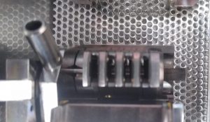
- Pick up the cartridge with a blunt tweezer and let it glide into the magazine (Figure 32). In the depicted image it is put in position 4.
- Use the straight egde of the white rotation tool to put the cartridge tightly into the magazine. The is a small resistance to overcome (Figure 33).
- Repeat above steps for up to 4 samples.
- Open the lock of the magazine (Figure 34).
- Use the white rotation tool to turn the magazine down (Figure 35).
- Use the flat side of the rotation tool to push the magazine into its vessel (Figure 36).
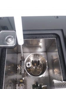
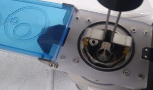
- Once the magazine is in its vessel use the white rotation tool to lift up the vessel (Figure 37).

- Once the magazine vessel is upright, fill it up with liquid nitrogen, so that the whole magazine is covered. No need to fill it up to the rim of the vessel (Figure 38) Important: Before doing the next steps, make sure the microscope is ready for grid insertion, i.e. it is not making images at the moment.

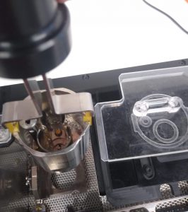
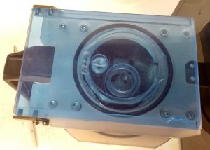
- Put the cryo cup next to the assembly workstation, have the pictogram on the lid oriented in the same direction as the magazine vessel; i.e. small and large circular structure (Figure 39)
- Pick up the magazine vessel with the large grabbing tool (Figure 40). Important: Ensure a good grid to not drop the vessel.
- Position the magazine vessel in the cryo cup (Figure 41). Note the proper orientation with the pictogram.
- Close the lid of the cryo cup and bring it to the microscope for insertion.
- Clean up after finishing and put all the tools back into its box and drawer.